background image

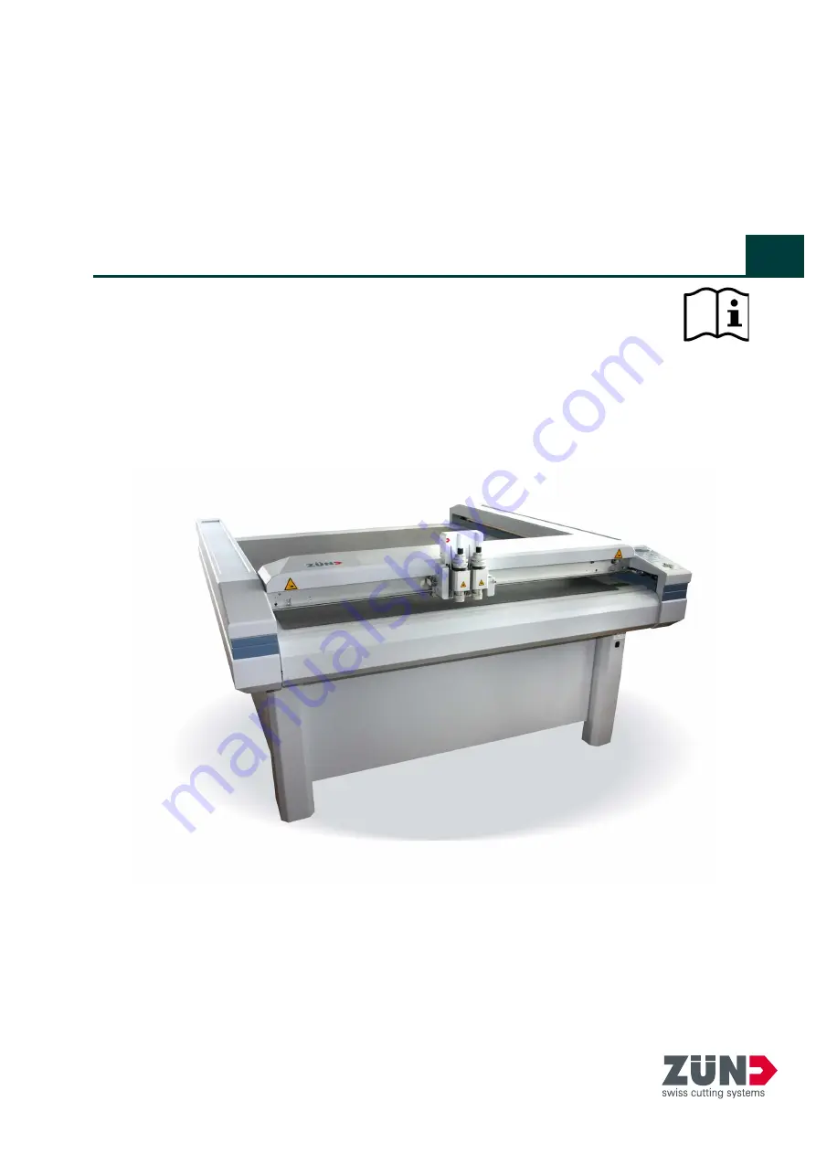
Digital flatbed cutter
PN Series

(S-800, M-800, M-1200, M-1600, L-800, L-1200, LR-1600, XL-800, XL-1200)

Operating manual

EN

Содержание L-1200

Страница 1: ...Digital flatbed cutter PN Series S 800 M 800 M 1200 M 1600 L 800 L 1200 LR 1600 XL 800 XL 1200 Operating manual EN ...

Страница 2: ... 6010800ff Original operating instructions Author Technical Editorial Department Zünd Systemtechnik AG Composition and publication Zünd Systemtechnik AG Copyright Zünd Systemtechnik AG Version Menu version Date Doc no ...

Страница 3: ...2 4 Overview 3 2 5 Layout and function 4 2 6 Intended use 5 2 7 Technical information 5 2 7 1 Dimensions and weights 6 2 7 2 Mains connection 7 2 7 3 Environmental conditions 7 2 7 4 Control unit 7 2 7 5 Performance 7 2 7 6 Emissions 8 3 Safety 1 3 1 General 1 3 2 Proper use 2 3 3 Examples of improper use 2 3 4 Hazard warnings important instructions 3 3 4 1 Explanation of the hazard warning 3 3 4 ...

Страница 4: ... by laser beam laser pointer 24 3 23 Safety instructions for operators 24 3 24 Safety precautions for service personnel 25 3 25 Disposal 25 4 Controls and operation 1 4 1 Controls 1 4 2 Operating modes 2 4 3 Operating unit 3 4 3 1 Description of keypad 4 4 3 2 Description of the display 6 4 3 3 Command input 6 4 3 4 Setting the language 7 4 3 5 Setting unit of length 7 4 3 6 User defined function ...

Страница 5: ... 5 Maintenance jobs 8 6 5 1 Maintenance position 8 6 5 2 Visually inspect machine for damage 8 6 5 3 Clean the machine 8 6 6 Instructions for disposal 10 6 7 Starting up after periods at a standstill 10 6 8 Transport and storage 11 6 8 1 General 11 6 8 2 Transport damage 11 6 8 3 Storage 11 6 9 Accessories spare and wearing parts 12 6 9 1 Supplied accessories 12 6 9 2 Recommended spare and wearing...

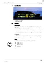
Страница 6: ...PN series frame version 0 4 110002 001 11 2009 jmu 0 ...

Страница 7: ...tion that is suited to your individual requirements in terms of speed and quality The availability of the most up to date technology thanks to constant develop ments Our approach Constant and intensive cooperation with successful users is a prerequisite for inno vative and practical solutions We are therefore grateful for any comments or sug gestions on how we can improve Contact Zünd Systemtechni...

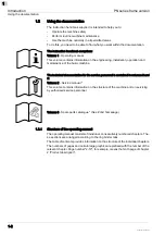
Страница 8: ...ic machine The technical documentation for the service personnel is contained in volumes 2 and 3 Volume 2 Service manual This volume contains information on the structure of the machine and on servicing by authorised service personnel Volume 3 Spare parts catalogue See Zünd homepage 1 2 1 Structure of the operating manual The operating manual consists of individual consecutively numbered chapters ...

Страница 9: ...essories There are a number of optional accessories available for the machine Any descrip tion relating to an optional accessory is identified in the operating manual by the symbol Close fix tighten in Open release loosen out Higher Lower Task Steps to perform Result Outcome of the tasks performed Prerequisites for performing a task List of tools ...

Страница 10: ...d section See chapter 2 4 Overview of the machine for example leads to chapter 2 Product description which contains section 4 Overview of the machine Sketches and schematic representations These are provided for general information and do not necessarily correspond to the latest version of the machine Dimensional information Dimensional information is listed in the SI US unit system according to t...

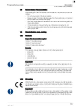
Страница 11: ...2 Service manual Volume 3 Spare parts catalogue Execution This operating manual makes reference to the following standards EN 62079 EN 62023 ANSI Z535 6 EN ISO 12100 2 Important EU standards and guidelines which are applied are listed in the declaration of con formity In the interests of our customers we reserve the right to make changes as a result of technical improvements This document therefor...

Страница 12: ...n PN series frame version Standardisation tests marking 1 6 110003 001 11 2009 jmu 1 Directive 2006 42 EC and or without CE marking As a result the declaration of con formity must be issued again by the purchaser ...

Страница 13: ...permission Offenders will be liable for damages 1 8 Troubleshooting hints and tips Important You can find information about troubleshooting and useful hints and tips on the Zünd homepage www zund com 1 9 Documented cutter models This documentation applies for the following types of PN series cutters 1 10 Publishing details Name Operating manual for PN series cutters side support version Compositio...

Страница 14: ...Introduction PN series frame version Publishing details 1 8 110003 001 11 2009 jmu 1 ...

Страница 15: ...Important technical data General technical description of the device Directional information Directions such as right left or front back are specified according to the opera tor s view of the machine during operation Fig 2 1 Directional information Important information Important Refers to user tips and useful information which enhance the usability and prolong the service life of the machine and ...

Страница 16: ...e following purposes As an output device for CAD CAM data For processing and labelling materials arranged on the table Aside from this the intended use and the limits of the application are as follows Depending on the tools and material feed system available Described in the chapters Tools Modules and Material transport 1 Manufacturer 2 Machine type 3 Serial number 4 Voltage 5 Power 6 Frequency 7 ...

Страница 17: ...verview Fig 2 3 Overview 1 Beam 2 Head carriage with tool head right side panelling 3 Side panelling 4 Operating unit 5 Table 6 On off switch 7 Distribution box 8 Side parts 9 Compressor 10 Electronics unit 11 Removable cover 12 Vacuum pump s 13 Vacuum cleaner 14 Boom 15 Maintenance unit ...

Страница 18: ...ety trip switches The carriage is part of the beam and is used for carrying the tool heads A central locking screw enables quick and trouble free head exchange The carriage drive is integrated into the beam and comprises A servo controlled DC motor A slip free steel band drive The standard tabletop is made from easy care plastic In practical use it is a proven solution with low noise emission and ...

Страница 19: ...ltage using a voltage selector The distribution box is operated using the On Off switch and enables All components of the plotter system to be switched on off simultaneously Consumer loads to be switched on by the software Distribution of individual consumers to different mains phases Compressor extractor and vacuum pump s with accessories Are adapted to the plotter version and to the material fee...

Страница 20: ... 800 mm 1355 x 1246 x 995 mm 250 kg 1 060 mm M line M 800 M 1200 M 1600 1300 x 800 mm 1300 x 1 200 mm 1300 x 1 620 mm 1841 x 1246 x 995 mm 1841 x 1646 x 995 mm 1841 x 2066 x 995 mm 310 kg 370 kg 460 kg 1 550 mm 1 550 mm 1 550 mm L line L 800 L 1200 LR 1600 1800 x 800 mm 1800 x 1 200 mm 1800 x 1 650 mm 2361 x 1246 x 995 mm 2361 x 1646 x 995 mm 2400 x 2280 x 1060 mm 490 kg 500 kg 570 kg 2 050 mm 2 0...

Страница 21: ...tem X Y T Z Variable look ahead vector control Software Interface 1MB input buffer with replot function 2 7 5 Performance Precision Adjustable voltage for electronics unit only 100 V 115 V 230 V tolerance 10 Mains frequency 50 60 Hz Power consumption one phase without vacuum pump 700 VA Current consumption one phase without vacuum pump 2A Operating temperature 10 C to 32 C Storage temperature 20 C...

Страница 22: ...against noise and contamination dust solvents material resi dues etc for each tool head are specified in Part 3 Electromagnetic emissions The plotter meets the requirements of the following standards EN 50081 2 EMC emission standard for industrial environments EN 50082 2 EMC interference resistance standard for industrial environments Please ask the manufacturer if you wish to refer to the test re...

Страница 23: ...Explanation of the meaning of symbols and pictograms which are used in this manual and in signs on the machine Location of safety and monitoring devices on the machine Information on protective equipment required and of requirements for operators and maintenance personnel Specific activity related and situation related safety instructions are given in the cor responding procedures in the following...

Страница 24: ...e safety instructions in this operating manual are observed The operating conditions are adhered to and the prescribed materials are used 3 3 Examples of improper use Improper use of the machine can Cause injury Result in serious damage to the machine Lead to loss of warranty Improper use of the machine includes among other things Any structural modification to the machine carried out without writ...

Страница 25: ...ction Warning Refers to a dangerous situation Refers to operational and service risks Warns of serious effects on health and safety including life threatening injuries Attention The safety instruction Caution Refers to a dangerous situation Refers to operational and service risks Warns of minor injuries and other serious damage to the machine and secondary damage Attention The safety instruction C...

Страница 26: ...y of the material to be processed from the ma nufacturer Use a suitable extraction unit or take other appropriate action accordingly Hazard warnings consist of the following units 1 The hazard symbol of the appropriate signal colour 2 The signal word corresponding to the danger resulting from the situation 3 The description of the danger 4 The description of the consequences which could result fro...

Страница 27: ...e Ensures that servicing and maintenance is carried out according to the mainte nance schedule Notifies the manufacturer of any accident involving the machine that results in se rious injury or substantial material damage Removes the machine from service immediately if defects arise that are detri mental to its operational safety Operators and service personnel Wear the necessary personal protecti...

Страница 28: ...by other manufacturers may only be used with the machine with the writ ten approval of the manufacturer Only service personnel authorised by the manufacturer are permitted to install commission maintain and repair the machine Before carrying out any maintenance repair and modification work Switch the machine off using the on off switch and secure with a lock Prevent the machine being switched on i...

Страница 29: ...n the cutter 1 Tool head 2 Beam 3 Working area on table 4 Side covers near beam openings 5 Base plate live parts a Openings at the end of the side covers in beam end position b Areas between side covers and tool head in end position c Clearance between beam and table d Area between tool head and table and area around the tool used ...

Страница 30: ...Safety PN series frame version Danger areas 3 8 110005 001 11 2009 jmu 3 3 9 2 Danger area during processing Fig 3 2 Danger area during processing 1 Danger area ...

Страница 31: ...he manual initialisation Do not reach into the danger area during the manual initialisation Use the automatic initialisation function for the initialisation Fig 3 3 Danger area during the installation e g R45s Safety distance during the manual initialisation The safety distance b for operating personnel during manual initialisation is 25 cm Do not reach into the danger area during the initialisati...

Страница 32: ... other personnel The safety distance for other personnel extends over the surface of the cutter plus a distance of at least one metre Working and traffic area The working and traffic area extends over the surface of the cutter with fittings and options plus a distance of at least one metre Use with conveyor extension When using a cutter extension the loading and removal of material is permitted ou...

Страница 33: ...ponsible for replacing missing illegible safety signs on the machi ne The appropriate safety signs can be requested from your service partner 3 11 2 Position of the safety signs Fig 3 5 Safety signs Important safety signs on the machine must be followed Otherwise this could result in serious injuries or death Special module or tool specific signs can be found in the relevant operating manual 1 Dan...

Страница 34: ...pecific meanings Are located wherever certain behaviour is prohibited due to it being potentially dangerous Prohibition signs Are round and red coloured Are located wherever certain behaviour is prohibited due to it being potentially dangerous Order signs Are blue and circular Stipulate the wearing of personal protective equipment to protect against ha zards Fire protection signs Are rectangular a...

Страница 35: ...e triangular and yellow coloured Are intended to draw attention to objects and circumstances which represent a potential danger to life and limb Danger of hand injuries crushing Danger of hand injuries severing Danger of electrical safety hazard Laser beam warning Caution use specified fuses ...

Страница 36: ... rear side of the beam Important The light barriers are only active in ONLINE mode They do not work during initialisation or in OFFLINE mode Protective trip switches and light barriers are part of a self monitoring safety shut down system If an obstruction is detected by the protective trip switches or the light barriers An EMERGENCY STOP is activated The machine switches to OFFLINE mode An error ...

Страница 37: ...t remains switched on Attention Pressing the emergency stop switch can damage the cutter Do not press the emergency stop switch to switch off the machine in routine opera tion Important To unlock an activated emergency stop switch after regaining operational safety turn the switch anticlockwise Safety cut off feature When an overload occurs or an axle drive X Y T Z is blocked The emergency stop is...

Страница 38: ...maintenance and servicing work Personal protective equipment comprises Work clothes service personnel Protective goggles operators service personnel To provide protection from particles during cutting operations To protect the eyes from dangerous radiation To protect the eyes from chemicals Protective gloves where injury is possible due to Burns Sharp or pointed objects Chemical resistant protecti...

Страница 39: ... to be processed Do not lay your hands on side covers Do not lean over the working surface Avoid leaving long hair loose and wearing loose clothes and ties These precautions specifically apply if the cutter can be switched into ONLINE ope rating status by the CAD CAM system 3 14 2 Gathering impacts of foreign objects Foreign objects on the table are grasped and pushed away by the bar and the tool ...

Страница 40: ...on in the ONLINE operating status of the machine Be extremely careful when changing the tool inserts Do not enter the working area during the initialisation and during operation in the ONLINE operating status 3 15 Risk of burns Certain materials metals and tools router reach very high temperatures during processing Possible consequences Burns on the limbs Precautions Allow workpieces to cool befor...

Страница 41: ...c shock The machine is operated with a mains voltage of 380 V system frequency of 50 60 Hz Safety instructions Only trained service personnel are authorised to open switch boxes and electro nics units Ensure that mains cables are protected against mechanical loading and are laid so that they are free from strain Replace damaged cables immediately ...

Страница 42: ...t filters if you are routing processing hazardous materials Zünd offers suction systems which meet the following regulations as accessories The extraction of hazardous dusts with a maximum concentration at work of up to 0 1 mg m3 and the extraction of wood dusts of dust class M The extraction of dusts conforming to dust class H 3 18 Risks arising from the processing of toxic hazardous materials Wa...

Страница 43: ...tercourses or the sewage system Explanation of the hazard label Safety regulations and protective measures Dispose of waste materials in accordance with current national environmental protection regulations In case of doubt check the appropriate disposal methods with your local collection point or recycling centre Collect different chemicals in separate containers Hazard label for substances that ...

Страница 44: ...leaning agents operating fluids Safety datasheets of the substances in question can be downloaded from the Zünd homepage www Zund com Safe handling of chemicals Disposal Dispose of chemicals in accordance with national regulations Store chemicals in tightly closed containers in a cool dry place between 5 C and 30 C Protect the containers from heat and direct sunlight Provide good ventilation inclu...

Страница 45: ...Flying sparks or electrostatic charges result in the risk that there will be dust explo sions during the extraction of different materials Obtain information about the risk of explosion when processing the type of ma terial that you are using If necessary adjust the extraction to the required regulations Fire classes Refer to the following table to find out which type of fire extinguisher is used ...

Страница 46: ... extingu isher Do not use inflammable cleaning agents to clean the machine Store all processing materials in the proper manner in accordance with local gui delines 3 22 Danger caused by laser beam laser pointer Class 2 lasers are used as laser pointers Momentary irradiation of the eyes as can occur if you accidentally look directly at the laser is not dangerous In addition de pending on the constr...

Страница 47: ...sposal Disposal Information about proper disposal Identifies toxic substances that are harmful to the environment Relates to the disposal of harmful substances Warns against disposal with domestic waste or environmental pollution caused by hazardous substances and objects contaminated with such substances Measures for disposal Zünd cutters correspond with the requirements of the German Electrical ...

Страница 48: ...Safety PN series frame version Disposal 3 26 110005 001 11 2009 jmu 3 ...

Страница 49: ... Controls and operation 4 1 Controls Fig 4 1 Controls The control panel Fig 4 1 item 1 Indicates the operating mode Enables commands to be input and parameters set for the machine Reports on errors and failures Use the On Off switch to switch the entire cutter system on off Fig 4 1item 2 ...

Страница 50: ...s positioned OFFLINE mode In this mode The cutter system does not process CAD CAM data The data transferred is stored in the input buffer OFFLINE mode is used for Settings Checks Adjustments and calibrations on the tool head Tool changes Material changes on the vacuum plate and on the material feeding system ONLINE mode The operating panel Indicates the operating mode Is used for all key functions...

Страница 51: ...f an LCD and keypad A coordinate symbol shows the direction of the coordinate axes as viewed from the reference point on the vacuum plate 1 LCD display 2 Arrow keys 3 Clear key 4 Escape key 5 Enter key 6 Function block F1 F4 7 Numerical keys 8 PEN UP DOWN key 9 VACUUM key 10 REF key ZERO POINT 11 ONLINE key 12 Direction keys 4x 13 SHIFT key 14 Coordinates symbol ...

Страница 52: ...tep Go back to the higher menu level ESC key 4 Used for Terminating functions and inputs Calling up the highest menu level Function keys 5 Function keys F1 to F4 Are used for calling frequently used commands Are pre configured by the manufacturer Can be reconfigured by the user Numerical keys 7 Used for Entering command numbers Entering numerical values PEN UP DOWN key 8 For lowering lifting the s...

Страница 53: ...or more direction keys triggers an emergency stop The machine switches to OFFLINE mode In OFFLINE mode the beam and tool head can be positioned on the working sur face The assignment of keys corresponds to the direction of movement Simultaneously pressing a single direction key and the SHIFT key moves the beam and the tool head at a higher speed Simultaneously pressing a single direction key for e...

Страница 54: ...r an input or when pressing the CE ESC key 4 3 3 Command input Dedicated keys are assigned for frequently used functions such as for positioning the tool head setting the zero point etc see point 5 3 1 Mxxxx Menu USR 1 TOOL 1 x 0 Y 0 00 X 0 00 Display Description Mxxxx Menu Display of table type USR 1 User no 1 is selected TOOL 1x Tool no 1 is selected x Tool status x X Y Display of X and Y positi...

Страница 55: ...umerical keys to enter command number 531 Select desired language within the LANGUAGE submenu using the Up Down arrow keys and confirm with ENT key 4 3 5 Setting unit of length During commissioning the cutter system is set to a specific unit of length meter inch This setting is valid for all Length entries such as feed length Z depth and height Distances indicated on the display Internal calculati...

Страница 56: ...be adapted as the customer requires see command SET USER KEY 45 point 5 4 3 4 3 7 User parameters Nine different groups with user parameters can be called up in the USER submenu Each group contains presettings for different applications The corresponding group can be called up whenever a tool or material is changed there is no more need for time consuming settings on the operating panel The pre pr...

Страница 57: ...00 9600 9600 4 FORMAT Interface Parameter 8 NO NE 1 S 8 NO NE 1 S 8 NO NE 1 S 8 NO NE 1 S 8 NO NE 1 S 8 NO NE 1 S 8 NO NE 1 S 8 NO NE 1 S 8 NO NE 1 S 5 PROTOCOL Interface Parameter HW HW HW HW HW HW HW HW HW 6 BEFORE UP Pen delay 20 20 20 20 20 20 50 50 50 7 AFTER UP Pen delay 20 20 20 20 20 20 50 50 50 8 BEFORE DOWN Pen delay 20 20 20 20 20 20 50 50 50 9 AFTER DOWN Pen delay 20 20 20 20 20 20 50 ...

Страница 58: ... TO TOOL Spec Pen pulse OFF OFF OFF OFF OFF OFF OFF OFF OFF 1 6 FRE QUENCY Laser 1 7 RECESS POWER Laser 1 8 MAX POWER Laser 1 9 EXTERNAL GAS Laser 2 0 XY UP Accelera tion 4 4 4 4 4 4 4 4 4 2 1 XY DOWN Accelera tion 4 3 4 4 4 3 2 2 2 2 2 XY UP Speed 1000 1000 1000 1000 1000 1000 1000 1000 1000 2 3 XY DOWN Speed 1000 500 1000 1000 500 250 250 20 10 2 4 CORNER 40 40 40 40 40 40 40 40 40 2 5 PU ANGLE ...

Страница 59: ... POS DOWN Pen 2 0 0 0 0 0 0 0 0 0 35 TZ POS UP Pen 3 5 5 5 5 5 5 5 5 5 35 TZ POS DOWN Pen 3 0 0 0 0 0 0 0 0 0 35 TZ POS UP Pen 4 5 5 5 5 5 5 5 5 5 35 TZ POS DOWN Pen 4 0 0 0 0 0 0 0 39 TZ LIFT TIME Pen 1 300 300 300 300 300 300 300 300 300 40 TZ DOWN TIME Pen 1 300 300 300 300 300 300 300 300 300 39 TZ LIFT TIME Pen 2 300 300 300 300 300 300 300 300 300 40 TZ DOWN TIME Pen 2 300 300 300 300 300 30...

Страница 60: ...cted directly using the corresponding command num ber An LCD display informs the user about The current submenu Additional entry and selection opportunities for the commands The command menu contains commands for The complete cutter line All versions of the material feeding system All tool heads An error message is displayed if the cutter system is not suited for execution of a par ticular command...

Страница 61: ...C key There are two possibilities for navigating within this menu tree The cursor within the display of the operating panel can be Moved line by line using the Up Down arrow key Moved page by page using the Left Right key The display shows the corresponding submenu Once the cursor has been placed on the entry you can select it using the ENT key Instead of using the arrow keys the number of a subme...

Страница 62: ...E key cancels the selection and the cursor remains in the submenu Example for operation Selection of acceleration level 3 for moving with lifted tool Required command XY UP 1122 When the following inputs are made the associated submenu is indicated on the dis play Now the XY UP acceleration is set and basic level is shown again on the display You can find command numbers Within the command menu di...

Страница 63: ... settings 4 5 1 Job setup 1 SPEED 111 Use this submenu to set the moving speed of the machine There are online and offline parameters Online parameters are the values used when the plotter is in online mode i e when processing internal commands such as performing test plots etc Offline parameters are the values used when the plotter is being operated using the arrow keys XY DOWN 1111 Moving speed ...

Страница 64: ...hing on the plotter LIFTUP ANGLE 1132 You can set the angle for automatic corner lifting for the tool If a direction change of more than the set value is detected during the cutting pro cess the tool is raised automatically turned into the cutting direction and lowered again The default value is an angle of 40 degrees Angle value Enter using the numeric keypad Confirm with the ENT key Save as a us...

Страница 65: ... 1158 Z OFFSET 1159 KNIFE PRESSURE 116 The following commands are valid only for the cutting and drawing head type C2 CUT 1161 Here the contact pressure of the knife can be adjusted to the material to be cut Save the contact pressure as a user parameter not as a configuration parameter The de fault value is 100 gram CUT OFF 1162 Here the contact pressure of the knife for the cut function is set Th...

Страница 66: ...ODE 1172 This command controls the PD speed for specific tool heads and options Dispenser head Milling head Oscillating tool A constant maximum speed is important with these tool heads In the preset AUTO mode the speed is automatically adjusted by the head recognition If a speed of 200 mm s is set on the keyboard the tool reaches a maximum speed of 283 mm s in the MS Master Slave mode moving on a ...

Страница 67: ...C TIME 122 Determines the period between the lowering of the feeder elements and the start of feeding This time is required to create the vacuum or a cushion of air Important If you are operating the XL 1200LC cutter in combination with a blower set this value to 0 FEEDER 123 A foil sensor is assigned to each feeder element on the table If the plotter is confi gured for foil feeding the feeder ele...

Страница 68: ...rawing on paper from roll to roll Material fixing using a clamping bar and tensioning motor during feeding a win ding motor winds up the paper at the front Cutting cardboard from roll with or without winding up of the rest Material fixing by means of vacuum prior to feeding the plotter stops for the re moval of the cut parts during material feed a valve vents the vacuum and ac tivates it again aft...

Страница 69: ...on block 2 Set the parameters to suit the application Example Save configuration block 2 using ESC 12532 Once all settings have been made correctly it is possible to switch between block 1 and 2 using the TOGGLE CONFIG or LOAD CONFIG x function The configuration can also be changed using a software HPGL command MODE NO VACUUM 128 ROLL OFF CORE 1291 FIXING CLAMP B 1293 ROLL UP CORE 1294 MODE VAC VA...

Страница 70: ...errupts it All values and settings in this submenu are preset during installation and commissio ning of the unit and do not need should not be changed subsequently The parameters can be saved as configuration parameters 46 if necessary LOCK FEEDER 1264 Lock sheet feeder During the next feed a new sheet will not be taken up from the feeder The plotter transports only the material that is already on...

Страница 71: ...e display shows Now the cut material can be removed from the vacuum plate The material feed is carried out when the ENT key is pressed With NO VAC the material is fixed by the clamping beam and take up device without vacuum The vacuum is not activated during feeding Attention If the mode is NO VAC and the vacuum pump blower is switched on at the keypad the vacuum is not released during feeding err...

Страница 72: ...factor 2 ZOOM X 132 The zoom factor for the X axis is set here ZOOM FACTOR 133 The zoom factor for the Y axis is set here An output can be scaled easily by entering specific zoom factors for the X and Y axis With negative zoom factors the output is mirror reversed Zoom factors Enter using the numeric keypad Confirm with the ENT key Setting Material monitoring 4x 4 foil sensors for automatic foil f...

Страница 73: ...P1 and P2 on the axis of rotation axis e g ticks or the edge of the sheet The 2 points should be as far apart as possible to enable exact calculation ANGLE 1412 The angle of rotation can be entered if known ROTATION PT 1413 Sets the position of the rotation point by manually moving to it ADJUST PT 14131 The position of the rotation point can be entered directly using the keyboard ACTIVATION 1414 O...

Страница 74: ...E 2211 Use this command to specify the type of converter Possible settings AUTO MANU Important With the AUTO setting the converter transmits a confirmation to the machine after the switching on signal or when a preset speed is reached The data starts to be pro cessed only once this confirmation has been made successfully ROUTER DELAY 2212 A delay can be specified here if a converter without confir...

Страница 75: ...is inserted must be defined in this menu Possible inputs 0 1 2 3 4 Tool number Enter using the left right arrow keys or the numeric keypad Confirm with the ENT key Save as a configuration parameter if required FREQUENCY 2223 Valid only for EOT type tools Select high or low frequency for the EOT electric oscillating tool Possible settings HIGH LOW POT DRT EOT 2224 Operate POT in combination with an...

Страница 76: ... 4 Tool number Enter using the arrow keys left right or the numeric keypad Confirm with the ENT key Save as a user parameter if required CUTTING TOOL 225 The submenu for the cutting of foils WIDTH 2251 This command is valid only for cutting and drawing head type C2 P Use this com mand to specify the width for automatic foil cutting Input range 0mm to max width of working surface Desired width in m...

Страница 77: ... ter 30km drawing distance the machine stops automatically and displays a cor responding message LINK TO TOOL 2291 The tool number to be monitored is specified here Possible inputs 0 1 2 3 4 Tool number Enter using the arrow keys left right or the numeric keypad Confirm with the ENT key Save as a configuration parameter if required ACTUAL 2292 If a used tool ballpoint etc is inserted the distance ...

Страница 78: ... can be used depending on the tool application as a punch tool for drilling or as a groove tool to cut out V shaped groo ves Dependent on this you must define the tool here for punching PUNCH LEFT 2321 Defines if a punch tool is implemented here PUNCH RIGHT 2322 Defines if a punch tool is implemented here T75 MODULE 233 Refer to the description of the T 75 module GLUE MODULE 234 No function Settin...

Страница 79: ...s are active MODE off INTENSITY 1 CUT PRECISION 24 Depending on the tool heads and tools used inaccuracies may occur as a result of the sum of several manufactured in tolerances especially during cutting Example Tool head with knife Tool heads insert sleeves knife holders and even the knives themselves are sub jected to manufactured in tolerances When a knife cuts each cutting error is doubled wit...

Страница 80: ...eter for the Y direction here TEST CUT 2413 Performs a test cut ADJUST TANG 242 The tangential angle can be readjusted by up to 10 from the default setting the knife is positioned at an angle to the cutting edge Important Changing the tangential angle may damage the tool TEST PATTERN 243 POLYGON 2431 Cuts 2 octagons to check the corrective parameters If you place the two parts that have been cut o...

Страница 81: ...rently being used in which module RECALL SETTINGS 252 Recall a pre saved initialisation process tool parameter set SAVE SETTINGS 253 Save the parameter set for a specific tool in the module selected SPECIFY NEW TOOL 254 Create a new tool parameter set MODE 255 Select the tool manager mode off manual auto Z DOWN LIMIT 26 Set the down position limit for the module tool selected The Z down limit opti...

Страница 82: ... MANUAL FEED 324 The bar must be moved to the desired reference point using the arrow keys After activating the function the feeder elements are activated and the vacuum or hold down is released The material can be feed using the arrow keys To stop press the ENT key By default manual feed is set so that the material can be moved forward only By readjusting the basic settings negative manual feed i...

Страница 83: ...ed out For a restart enter the REPLOT command and press the ONLINE key Terminating replot mode Enter the CLEAR BUFFER command 331 WINDOW 34 The commands in this submenu enable users to limit the working area of the machi ne window All data and vectors outside this window are ignored Vectors which begin inside the window and end outside are clipped at the window boundary STATUS 341 Here the window ...

Страница 84: ...ma ximum speed and acceleration C2 TOOL 35 RELEASE TOOL 351 This command is available only for cutting drawing head type C2 The tool holder is released after the command input and can be removed from the cutting drawing head STATUS 36 SHOW STATUS 361 Indicates the current basic settings on the display When you press the downward arrow key the following appears on the display You can call the previ...

Страница 85: ... test plot Not all test plots can be stopped immediately Before each test plot the following message appears on the operating unit display DIN 3811 Plots the DIN TEST onto a DIN A3 sheet POLYGON 3812 Plots polygons over the complete working area of the table RANDOM LINE 3813 Travels continuously over random vectors with raised tool DIAGONAL 3814 Travels continuously over the diagonal of the active...

Страница 86: ... operating unit and the machine moves to this point during initialisation Normally one reference point starting point is used There are 3 different operating modes Standard mode Tandem mode Double sided mode Standard mode One reference point is used Tandem mode In tandem mode it is possible to set up or remove material from one side while the plotter is operating on the other side The appropriate ...

Страница 87: ...appropriate key The reference point May not be altered during a job Refers to the active tool or if installed the laser pointer When you press the REF key the following menu appears SET REFERENCE 1 3911 Reference point no 1 is set GO REFERENCE 1 3912 The machine moves to reference point no 1 CLEAR GO 3913 Deletes the reference point s and moves to the original reference point GOTO XY 3914 GOTO X 3...

Страница 88: ...ing unit Enter the WIDTH command The current vacuum width Is shown on the display Is indicated by the tool head with Pen 1 Move the tool head in the Y direction using the direction keys until the desired vacuum width appears on the display Press the ENT key to set the new vacuum width and move the tool head back to its original position Important When using the WIDTH command the vacuum width is al...

Страница 89: ...ment of the vacuum width Procedure Position the active tool to the desired vacuum width using the direction keys Press the VAC key and key 5 FOILCOVER 3926 This command is valid only for the LC 16 52 and LC 27 32 plotters LC 16 52 ZONE 3927 This command is valid only for the LC 16 52 plotters MOVE TO PARK 393 When using the command MOVE TO PARK the tool head moves to a specified po sition at the e...

Страница 90: ...n the park position the command is executed by pressing numerical key 3 on the operating unit SELECT TOOL 394 The commands in this submenu enable the active tool to be changed quickly Conditions The commands are assigned to a specific function key on the operating unit using the command SET USER KEY 45 TOOL 3941 This command increases the number of the active tool by 1 until the highest tool num b...

Страница 91: ...c keypad Confirm with the ENT key SET USERSTRING 44 In ONLINE mode the display shows the default text User 1 on the bottom line You can use the SET USERSTRING command to edit and store this text for each group of user parameters ENTER TEXT 441 Procedure Enter the ENTER TEXT command The display shows The arrowhead indicates the end of text Press the ENT key The arrowhead is replaced by a flashing c...

Страница 92: ...w assignment of function keys must then be saved as a user parameter The machine must be restarted in order to change the current function key assign ment SAVE CONFIG 46 This command saves the following settings ROLL OFF PARSER TYPE DISPLAY MODE PUMP OFF DELAY ROLL UP QUALITY MODE FIXING LANGUAGE SENSORS START USER OSCILLATION DELAY VAC TIME PASSEPARTOUT DELAY ...

Страница 93: ...rotocol SW TERMINAL CHECK 514 All data received via the interface is shown on the display but is not processed by the machine SCI DIAGNOSTIC 515 If the data transmission is interrupted the following settings can be used to call up test functions for data analysis The standard setting is 1 UNITS 52 You use this submenu to define the length unit for Length entries such as feed length Z depth and hei...

Страница 94: ...he arrow keys left right By entering the command number using the numeric keypad Confirm with the ENT key and save as a configuration parameter RIGHTS 533 This command is required only for service and test purposes LOCK SETTINGS 534 When using this command the machine works only with the preset parameters speed acceleration etc All HPGL commands that modify these parameters are ignored L BARRIER O...

Страница 95: ...vated using the On Off switch located beneath the operating panel After switching on The machine initialises The tool plotter then switches into OFF LINE mode In OFF LINE mode The machine stores all data transferred by the CAD CAM system All settings can be made to the tool and material feeding system Working material can be inserted or removed If you press the ON LINE key on the operator panel th...

Страница 96: ...and the material fee ding system in sections 3 and 4 Align the working material on the table and fix it with vacuum To do this press the VAC key and make the settings If necessary adapt reference point to material For this purpose press REF key and enter new reference point 4 6 4 Checks before processing operation Does the SETUP side in the plot file match the current tool configuration Are there ...

Страница 97: ...ote of The machine s serial number The error number indicated on the operator panel including the complete error message press ENT key several times for request You can find the serial number On the type plate of the cutter In section 1 General chapter 5 Conformity Once you have this information please phone Your service partner or Zünd representative in the first instance Zünd Systemtechnik AG Te...

Страница 98: ...heck RS232 settings on PC and plotter Comment This message is disabled when SCI diagnostic is set to level 1 or 2 Enter ESC 515 then use the key to select 1 or 2 and complete using ENT If Frame determines another error in the serial interface at the same time Frame is displayed at level 1 0103 Serial interface Buffer overflow Causes Plotter input buffer overflows transmission stop was ignored The ...

Страница 99: ...to reinitialise the plotter If this is not possible switch off the plotter and check the Z axis Comment Possible secondary error 0001 Hint Check the position sensor using test function 52 0307 AC fault Check AC Causes Error in the AC part of the system detected or the MC software version is older than the one on the AC system Action Use ENT to check for more information or call Zünd service if the...

Страница 100: ...f revolutions for a tool change to 16 or fewer revolutions 0401 HPGL Parser Unknown syntax Cause Invalid HPGL character in the plotfile noise on the data line Index ASCII Code of the cause Text Current HPGL command Action Check plotfile and interface It may be the case that sections of the plotfile were not transferred Remarks The current command is terminated This message is disabled when SCI dia...

Страница 101: ...f and on If the reason is not clear possible causes could be a interrupted emergency loop a defective master board a short circuit to a voltage 2 5 volts or noise If initiated in a test cycle a hardware error or noise caused the message Possible causes could be a short circuit against ground or case or a defective master board Hint See chapter Emergency stop in the description of the electronics S...

Страница 102: ...the menu was used even though the job has not yet ended Action Allow the job to finish or delete the buffer 1007 Tool DST Counter Change the tool Cause Work distance counter reached the maximum value Action Exchange the tool and set a new maximum ESC 2293 See the user manual for more information about this function 1201 Keyboard Fault A key is pressed Cause Pressed key detected when plotter is swi...

Страница 103: ... Cause The DRT Driven Rotary Tool current exceeded the preset limit for a while Once the current reaches the limit the tool is lifted if it falls under the limit the tool is lowered again This message is issued if the tool is lifted more than 1mm without any reduction of the current Action Check initialisation offset and down position according to the DRT manual Check if there is some material bet...

Страница 104: ...outer and extractor Troubleshooting 1 Turn off the cutter system 2 Check all connections to local mains Are supply cables undamaged and run unstressed Is the mains plug correctly inserted Are the upstream fuses in local installation working properly 3 Open plotter base On the tool plotter raise and detach the covering panel next to the on off switch Fig 5 1 Access to the distribution box 4 Check p...

Страница 105: ...other check mains inputs as follows Remove the relevant mains cable Unlock the fuse holder by pressing in the clips and pull it out Replace faulty fuse s spare fuses are included with the accessories Fig 5 2 Check the fuses Rating must be Identical for both fuses Adapted to the available mains voltage see next page Fig 5 3 Elements in the distribution box 1 AC input socket for Electronic unit Opti...

Страница 106: ... vacuum pump etc Fuse holder with 2 fuses 7 AC input frequency transformer optional 8 AC input extractor optional 9 Blank cover for standard version 10 Output 24 V to switch external devices on off optional 110 115 V 12 5 A slow blow Ø 5 x 20 mm AC current Fuse specifications 230 V 50 Hz 16 A SPT Ø 5 x 20 mm high breaking capacity 110 115 V 8 A FST Ø 5 x 20 mm 230 V 60 Hz 16 A SPT Ø 5 x 20 mm AC c...

Страница 107: ...er cables from the mains before handling any live components of the cutter Inspect replace fuses Loosen the fuse holder carefully using a screwdriver and remove it from the housing see illustration Remove the fuses from the fuse holder inspect them and replace as necessary Only use the replacement fuse types listed below Fig 5 4 Electronic box fuse holder 1 Version A 2 Version B ...

Страница 108: ...N series frame version Electronic box fuses 5 12 110008 001 11 2009 jmu 5 Replacement fuses Fuse holder with 2 fuses AC current Fuse specifications 230 V 4 A slow blow Ø 5 x 20 mm 100 115 V 8 A slow blow Ø 5 x 20 mm ...

Страница 109: ...out the maintenance jobs conscientiously at the specified intervals The inter vals are given in calendar periods or operating hours Maintenance recommendation The manufacturer recommends that a general inspection of the machine is carried once per year This interval can be reduced in the case of greater utilisation and load to the system Regular maintenance extends the lifetime of the cutter Provi...

Страница 110: ...ing personnel after appropriate training You must ensure that spare parts meet the technical requirements laid down by the manufacturer Original spare parts are always guaranteed to do so The wearing of protective clothing see Personal protective equipment clothing in Safety is obligatory during maintenance and cleaning work Keep unauthorised personnel well away from the machine during maintenance...

Страница 111: ...ion Always take care to protect the environment Observe the disposal regulations applicable in your country Dispose of spent operating materials correctly Disposal This concerns spent materials such as lubricants adhesives water oil mixtures maintenance unit and all devices that were in contact with these materials Observe the rules on environmental protection when disposing of spent materi als Co...

Страница 112: ...sed at a temperature range from 25 C to 120 C Gears To lubricate the gears a Teflon special grease is used for precision gears in order to reduce friction 6 3 4 Adhesives Gluing the conveyor belt Attention The instant adhesive used irritates the eyes skin and respiratory system Skin can be glued together in seconds During use wear protective gloves and protective goggles If adhesive comes into con...

Страница 113: ...ols This service and maintenance work is carried out by authorised service person nel of Zünd Systemtechnik Solid symbols z Service and maintenance work is the individual responsibility of the company operating the machine or its operating personnel Important If necessary carry out work before the stated intervals Change worn parts before the specified intervals as well The intervals are given in ...

Страница 114: ...nnections and tighten according to requirements if necessary Check levelling Check feed system Check cabling wiring and cable routing for signs of wear Vacuum plate Conveyor replacement Check levelling and adjust if required Check the correct functioning of the vacuum zone control Beam Check perpendicularity and align if required Check length compensation and adjust if required Feeding options Cle...

Страница 115: ... up oil according to specifications See operating instructions from the manufacturer Check water separator and drain water if necessary Drain condensate from air cylinder Check pressurised pipes for leaks eliminate any faults Check air intake filter replace if clogged Clean compressor Check piping for damage and tightness Check the function of the safety valve adjust if necessary Replace compresso...

Страница 116: ...e damage repaired immediately by authorised service personnel Daily checks Walk around the cutter and check the machine for damage Make sure that all the covers have been fitted Fit any covers that are missing 6 5 3 Clean the machine Zünd cutters are production machines that are subject to enormous amounts of stress on a daily basis Keeping the machine clean will help to keep operation as free fro...

Страница 117: ...rsion Cleaning and maintenance Maintenance jobs 6 9 110010 001 11 2009 jmu 6 Regularly daily remove all materials residues from the table the tools and mo dules Keep the environment clean free from material residues dust ...

Страница 118: ... free solder and be disposed of as electric waste You must also observe the following Country specific legislation and regulations on waste disposal No special measures are generally required when decommissioning the cutter system because no poisonous substances are used Assign a disposal company to remove and recycle the machine correctly 6 7 Starting up after periods at a standstill Important Be...

Страница 119: ... arranged with the customer However damage or loss in transit might occur nonetheless The plotter system should therefore be inspected for completeness and signs of da mage immediately upon delivery Inform the shipping company immediately if you notice external damage to the pa ckaging Describe the extent and cause of the damage Refuse acceptance of the shipment if such details are not acknowledge...

Страница 120: ...se contains Teflon based lubricant Oil 1 brush Back up fuses for the distribution box 5 for each required rating 1 Allen key 4 mm used to replace the tool head Special equipment for the tool and material feeding system 6 9 2 Recommended spare and wearing parts Pay attention to Special notes in sections 7 and 8 for the tool and material feeding system The plotter accessory list on the Zünd homepage...

Страница 121: ...tage value that has been specified The label shown above is located within the cutter base on The mains input of the distribution box The voltage selector of the electronics unit Attention Danger of damaging the machine The available local mains voltage must correspond with the voltage value specified on the rating label Inadmissible mains voltages could result in heavy damage to the cutter system...

Страница 122: ...ge selector of the electronics unit to the available mains voltage Change the fuses on the electronics unit or distribution box to correspond with the set voltage Replace system components with a dedicated mains connection vacuum pump s compressor extractor milling device etc with appropriate substitutes 1 Holder 2 Set voltage 230 115 100 V 3 Fuse holder 4 Fuse ...

Страница 123: ...PN series frame version Tools 7 1 100011 003 11 2009 jmu 7 7 Tools ...

Страница 124: ...Tools PN series frame version 7 2 100011 003 11 2009 jmu 7 ...

Страница 125: ...PN series frame version Tool heads 8 1 110008 001 11 2009 jmu 8 8 Tool heads ...

Страница 126: ...Tool heads PN series frame version 8 2 110008 001 11 2009 jmu 8 ...

Страница 127: ...PN series frame version Options 9 1 100015 001 11 2009 jmu 9 9 Options ...

Страница 128: ...Options PN series frame version 9 2 100015 001 11 2009 jmu 9 ...

Страница 129: ...PN series frame version Material feed 10 1 100012 003 11 2009 jmu 10 10 Material feed ...

Страница 130: ...Material feed PN series frame version 10 2 100012 003 11 2009 jmu 10 ...

Страница 131: ...PN series frame version Additional specifications 11 1 100014 003 11 2009 jmu 11 11 Additional specifications ...

Страница 132: ...Additional specifications PN series frame version 11 2 100014 003 11 2009 jmu 11 ...

Страница 133: ...PN series frame version Documents 12 1 100017 001 11 2009 jmu 12 12 Documents ...

Страница 134: ...Documents PN series frame version 12 2 100017 001 11 2009 jmu 12 ...

Страница 135: ...Service 13 1 100013 003 11 2009 jmu 13 13 Annex 13 1 After sales Service Responsible service point Machine number Important default settings Modifications Interface parameters Date of initial commissioning Responsible service engineer Signature ...

Страница 136: ...Annex PN series frame version After sales Service 13 2 100013 003 11 2009 jmu 13 Acceptance certificate from customer Date Signature ...

Страница 137: ... 11 2009 jmu 13 13 2 Service and maintenance works In order to conserve the value of your plotter system carry out one service per year All service maintenance and repair works must be entered and confirmed into the table below by the service technician Date Signature Remarks ...

Страница 138: ...Annex PN series frame version Service and maintenance works 13 4 100013 003 11 2009 jmu 13 Date Signature Remarks ...

Страница 139: ...PN series frame version Annex Service and maintenance works 13 5 100013 003 11 2009 jmu 13 Date Signature Remarks ...

Страница 140: ...Annex PN series frame version Service and maintenance works 13 6 100013 003 11 2009 jmu 13 Date Signature Remarks ...

Страница 141: ...PN series frame version Annex Service and maintenance works 13 7 100013 003 11 2009 jmu 13 Date Signature Remarks ...

Страница 142: ...Annex PN series frame version Service and maintenance works 13 8 100013 003 11 2009 jmu 13 ...

Отзывы: