ZMC408SCAN Motion Controller Hardware Manual V1.5
3.
Please use STP, especially in bad environments, and make sure the shielding layer is
fully grounded.
5.2.
Basic Usage Method
1.
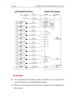
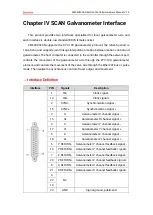
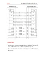
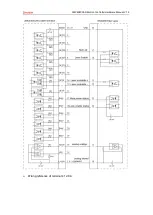
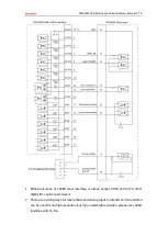
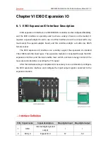
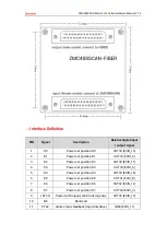
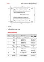
Please wiring correctly according to above wiring description.
2.
Please select one interface among EtherNET, RS232 (default parameters can be
directly connected) and RS485 (default parameters can be connected directly, need
to use adapter head for hardware) to connect ZDevelop.
3.
T
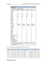
hrough “ZDevelop/In, Op window to operate and watch relative IOs.
4.
T
hrough “ZDevelop/AD/DA wi
ndow to operate and watch relative analog inputs and
outputs.
5.
In ZDevelop, send online command “PWM_FREQ (PWM No.) = frequency, PWM_DUTY
(PWM No.) = duty cycle.
Refer to BASIC routine:
B
ASE (4, 5) ‘select axis Scan 0, Scan 1 relates to
axis 6 and axis 7
A
TYPE = 21, 21 ‘select axis 4 and axis 5 as galvanometer axes type
U
NITS = 200, 200 ‘set pulse amount of axis 4, 5 as the unit of 200 bit
Dpos = 0, 0
Corner_Mode = 2, 2 ‘set axis corner deceleration mode is used fo
r corner delay
Decel_Angle = 30*PI/180, 30*PI/180
Stop_Angle = 90*PI/180, 90*PI/180
Z
smooth = 1000, 1000 ‘in galvanometer Scan instruction, Zsmooth is the max
delaying time 1000us when in corner delaying
F
orce_Speed = 100, 100 ‘in galvanometer Scan i
nstruction, Force_speed is axis 4/5,
and the Scan motion speed is 100*200 bit/s
M
oveScanAbs (0,0) ‘galvanometer moves to center origin position
Base (4, 5)
A
out (0) ‘set laser power is 50% for 12
-bit analog output 0, 0-10V
relates to 0-100% power.
O
p (29, ON) ‘open laser to enable IO
Содержание ZMC408SCAN
Страница 1: ......
Страница 52: ...ZMC408SCAN Motion Controller Hardware Manual V1 5 Wiring reference of terminal s 12 DA...

