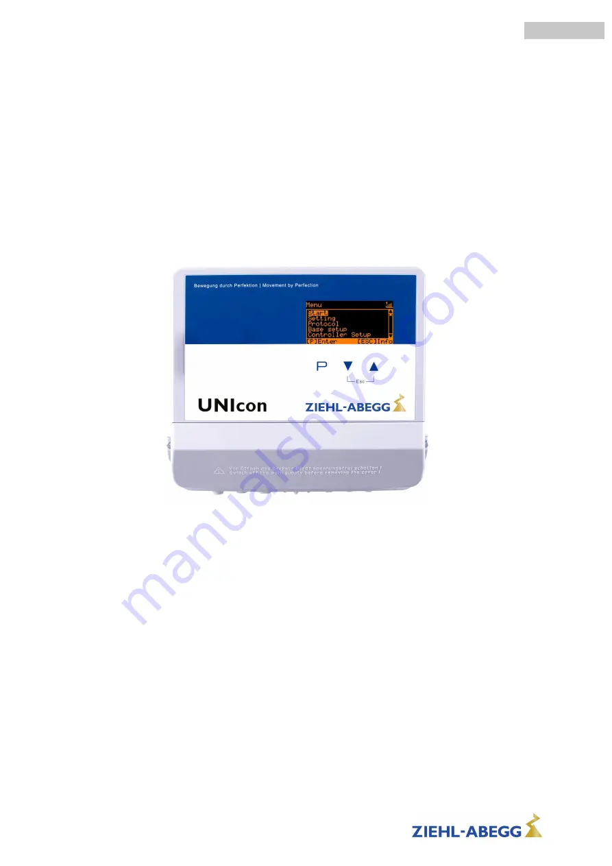
UNIcon MODBUS Master
CXE/AV(E), CXG-24AV(E)
Universal control module
Operating Instructions
Keep for reference!
Software version: D3614A from Version 10.02
L-BAL-E207-GB 1723 Index 003
Part.-No.
english
Страница 1: ...UNIcon MODBUS Master CXE AV E CXG 24AV E Universal control module Operating Instructions Keep for reference Software version D3614A from Version 10 02 L BAL E207 GB 1723 Index 003 Part No english ...
Страница 2: ... installation 9 5 1 Safety precautions 9 5 2 EMC compatible installation of control lines 9 5 3 Mains connection 9 5 4 Signal input or sensor connection E1 E2 10 5 5 Control outputs 0 10 V A1 A2 10 5 6 Voltage supply for external devices 24 V GND 10 5 7 Digital inputs D1 D2 11 5 8 Relay outputs K1 K2 11 5 9 RS 485 interfaces for MODBUS RTU 11 5 9 1 Addressing member MODBUS Master Interface 13 5 10...
Страница 3: ...0 9 8 Menu group Info 51 9 9 Controller Setup 53 9 9 1 PIN protection activate PIN0010 53 9 9 2 Set protection activate PIN 1234 53 9 9 3 Save user settings restore with PIN 9090 53 9 9 4 Sensor Alarm ON OFF 54 9 9 5 Limit 54 9 9 6 Minimum speed cut off 55 9 9 7 Reverse action of the control function 55 9 9 8 Controller configuration 56 9 9 9 Group control 57 9 9 9 1 Variant 0 One controlled group ...
Страница 4: ...tion depending on offset to Setpoint 82 9 12 Timer 83 9 12 1 Timerfunction 83 9 12 2 Setting of time and date 85 9 12 3 Automatic summer time 85 9 12 4 Enter switching times 86 9 12 5 Inverting timer function 88 9 12 6 Overwrite timer function 88 9 12 7 Adjustment of the real time clock 88 9 13 MODBUS Slave 89 9 14 MODBUS Master 90 9 14 1 Automatic addressing 90 9 14 2 Manual addressing 90 9 15 Me...
Страница 5: ...tion contained in data illustrations or drawings provided ZIEHL ABEGG SE is not liable for damage due to misuse incorrect use improper use or as a consequence of unauthorized repairs or modifications 1 4 Copyright These operating instructions contain copyright protected information The operating instructions may be neither completely nor partially photocopied reproduced translated or put on data me...
Страница 6: ...ote the instructions of AEL DLG VdS 2 4 Requirements placed on the personnel due diligence Persons entrusted with the planning installation commissioning and maintenance and servicing in connection with the frequency inverter must have the corresponding qualifications and skills for these jobs In addition they must be knowledgeable about the safety regulations EU EC directives rules for the prevent...
Страница 7: ...t for their properly functioning condition The assembly instructions and or operating instructions are always readily available at the location where the device is being used are complete and are in legible condition These persons are regularly instructed in all applicable questions regarding occupational safety and environmental protection and are knowledgeable regarding the assembly instructions...
Страница 8: ...weight walls can result in extremely high shock loads Therefore we advise you to decouple the devices from the wall Do not allow drilling chips screws and other foreign bodies to reach the device interior The device should be installed in a location where it will not be disturbed but at the same time can be easily accessed Care must be taken to avoid direct radiation from the sun Type CXE AV CXG 2...
Страница 9: ...ause energized exposed parts are present inside the device Disregarding this regulation can lead to severe personal injury The required protective earth connection is established using screws between the housing parts in metal terminal space covers and housing casings Commissioning is only permissible after these screws have been properly attached The device owner is responsible for the EMC of the...
Страница 10: ...to electric current Never apply line voltage to analog inputs 5 5 Control outputs 0 10 V A1 A2 The analogue outputs can be used to activate a speed controller with 0 10 V input for example Fans with integrated controller and 0 10 V input can be activated directly Analog output 1 terminals A1 GND Controlled 0 10 V output for control circuit 1 factory setting function 2A Analog output 2 terminals A2...
Страница 11: ... for MODBUS Master applications Pre programmed function is output from control circuit 1 1 Control signal 2A e g for activating speed controllers for fans or fans with integrated controller and MODBUS interface member MODBUS Master The programmable functions correspond to the functions for the analogue outputs described in the IO Setup Automatic addressing of members via a patented procedure It is...
Страница 12: ...g vsd Recommended wire types 1 CAT5 CAT7 cables 2 J Y St 2x2x0 6 telephone wire 3 AWG22 2x2 twisted pair Max allowed wire length 1000 m CAT5 7 500 m Shielding The use of shielded cables is normally not demanded but offers high protection against electro magnetic interferences especially high frequencies However the effectiveness of the shield depends on careful installation of the line If shielded...
Страница 13: ...vice by an external terminal or a PC Alternatively the addressing can be done manually by a separate hand held terminal or PC software the appropriate number of members must then be entered on the MODBUS Master menu group MODBUS Master BUS Slavecount Information If a repeater is necessary and automatic addressing should be carried out only the repeater of the Z G 1NE type can be used only it can r...
Страница 14: ...embers via the terminals A D B D GND and ID1 ID2 Networking with RJ45 patch cable by usage connection box for ECblue part no 380085 13 03 2013 v_modbus_master_autoadr_zabox vsd 4 32 1 BUS1 BUS2 BUS1 BUS2 BUS1 BUS2 GND ID1 A D B D 8 7 6 5 4 3 2 1 RJ45 RJ45 RJ45 MODBUS Slave MODBUS Slave MODBUS Slave MODBUS Master 1A 1D 1B 1D 2A 2D D1 ID GND 2B 2D D2 GND A2 24V A1 GND GND 2 3 Connection to the MODBU...
Страница 15: ...ctions The control voltage connections 50 V relate to the joint GND potential Exception relay contacts are potential free CXE AV E 1 230 V 2 400 V There is a potential separation between the control voltage connections and the earthed conductor It must be ensured that the maximum external voltage at the control voltage connections cannot exceed 50 V between GND terminals and PE earthed conductor I...
Страница 16: ...1 210 PT1000 E1 Temperature control airconditioning and refrigeration preset set point 20 0 C P band 5 0 K 2 02 Sensor KTY81 210 PT1000 E1 Temperature control depending on outdoor temperature preset set point 5 0 C P band 20 0 K 2 03 Sensor KTY81 210 PT1000 E1 Temperature control with additional functions shutter and heating 2 04 1x Sensor KTY81 210 PT1000 E1 1x Sensor KTY81 210 PT1000 E2 Temperat...
Страница 17: ...the mode This influences the output with function 2A A second control circuit with separate actual value measuring and separate output can be activated additionally if required Control circuit 2 influences the output with function 8A Analog output A2 factory setting IO Setup MODBUS Master interface member menu Operation with a second control circuit is not possible in the following modes 1 01 1 02 2...
Страница 18: ...is added to the parameters for control circuit 1 Example Second control circuit Pressure control condensers E2 function 9E Mode 2 01 for temperature control via control circuit 1 Setting 1 Setpoint 1 Setpoint 1 for control circuit 1 Setting range with passive sensor type TF PT1000 50 0 150 0 C Factory setting 20 0 C 20 0 C 1 Setpoint 1 Setting 1 Setpoint 2 Setpoint 2 for control circuit 1 Setting ...
Страница 19: ...omatic control without function speed setting in menu Speed manual OFF 1 Manual mode Setting Speed manual Speed Manual mode for control circuit 1 Setting range 0 1 Max Speed Factory setting 100 100 1 Speed man Function extension for digital inputs D1 and D2 in operation with second control circuit D1 D2 Function Description E1 E2 4D The output for control circuit 2 is set additionally to A2 to A1 ...
Страница 20: ... GND E2 GND External Setpoint via external signal instead of Setpoint 1 The external Setpoint function must be activated in base setup 1E for E2 function The active external Setpoint value is displayed in the info menu group External speed setting in manual operation The external manual operation function must be activated in the basic settings 2E for E3 function Switchover between settings on the...
Страница 21: ... OFF OFF Base setup Mode 1 01 1 02 2 01 2 03 2 04 2 02 2 05 3 01 3 02 3 03 3 04 4 01 4 02 4 03 5 01 5 02 6 01 E1 Analog In 1 01 0 10 V TF TF TF 0 30 MBG 0 30 MBG DSG200 4 01 DSG200 4 02 4 03 DSG50 0 1 MAL Number steps 1 02 0 Step 1 value 1 02 20 E1 Refrigerant 3 02 R503 3 04 R503 E1 K Factor 75 E2 Refrigerant 3 04 R503 Setting Set Internal1 1 01 80 Setting direct 1 02 80 Setting Step 1 02 0 Setpoi...
Страница 22: ...eating operation 7 Moon Symbol for set point 2 8 Alarm symbol fault message alternating with actual value display 9 Modulation control circuit 1 10 Modulation control circuit 2 if activated 11 STOP Symbol enable 12 Position of the menu in the menu group 13 List of the menu groups B Main menu Display after the Esc key combination is used to exit the actual value display Select the desired menu grou...
Страница 23: ...ller Setup Select the desired menu group with the keys text highlighted and open with the P key P Enter ESC Info Start PIN input PIN input e g for resetting to basic factory setting P Edit ESC Menu Start GB Language In the menu point Language display language can be selected One returns to the menu group Start using the Esc shortcut keys P Edit ESC Menu 8 3 Example for programming mode 2 01 in Bas...
Страница 24: ... Controller Setup PIN protection OFF If PIN protection is activated ON the service menu remains enabled after input of PIN 0010 as long as one is pressing keys If no keys are pressed for ca 15 minutes the PIN is automatically erased i e the service level is blocked To make adjustments press the P key after selecting the menu item If the previously set value starts to ash it can be adjusted with th...
Страница 25: ...etup P ESC P ESC P ESC P ESC P ESC Info Start Setting Protocol 1 22 Base setup Controller Setup 0 Set external1 PIN input 80 Set Internal1 Sensor1 OTC 000022 45 10 1 01 Mode OFF PIN Protection Start Setting Protocol 2 22 Base setup Controller Setup D Language Setpoint2 MODBUS Komm OTC 000018 05 10 0 10V E1 Analog In OFF Set protection Start Setting Base setup Controller Setup OFF US units 0 Min Sp...
Страница 26: ...vent of a sensor fault Activate limitation of modulation via digital input or timer of time switch Configuration of control parameters group control IO Setup Configuration and function assignment for analogue outputs digital inputs relay out puts Function MODBUS interface COM2 for MODBUS Slave or MODEM SMS Limits Limit messages depending on modulation setting signal or sensor signal offset to setpoi...
Страница 27: ...4 20 mA Inverting E1 BUS Modus IO Setup Factory setting 0 10 V 0 10V E1 Analog In Base setup E2 Function only for special applications Analog input 2 E2 factory set at OFF For operation with a second setting signal and switch over by potential free contact E2 Function Ext Setpoint 1E Necessary function for digital input E1 E2 4D IO Setup For operation with a second signal and automatic control at ...
Страница 28: ...rnal Signal OFF Setting Set Intern1 ON Set external1 Diagram setting signal and output voltage Idealized principle diagram 0 1 2 3 4 5 6 7 8 9 10 10 9 8 7 6 5 4 3 2 1 0 0 2 4 6 8 10 12 14 16 18 20 20 18 16 14 12 10 8 6 4 2 0 4 5 6 7 2 8 8 10 4 12 13 6 15 2 16 8 18 4 20 20 18 4 16 8 15 2 13 6 12 10 4 8 8 7 2 5 6 4 0 10 V 10 0 V 0 20 mA 20 0 mA 4 20 mA 20 4 mA Min Min 0 Max 100 Min 35 Max 85 28 03 2...
Страница 29: ... Step 1 value 5 Setting range 0 100 Factory setting Number steps 0 Factory setting 20 40 50 60 100 Number steps 1 5 Step 1 value Menu group setting only when needed Main menu Setting Setting Protocol Base setup Controller Setup IO Setup Setting Setting direct at Number steps 0 Base setup If the setting is to be made during operation directly with the keys no setting is necessary here setting in op...
Страница 30: ...ing range 0 programmed number steps Factory setting 0 5 Setting Step Switching over to the protected Info menu group takes place automatically after approximately 15 minutes if no key is pressed Possibilities for early activation of PIN protection Select the Info menu group and confirm with the P key Press the Esc key combination several times until the Setting direct or Setting Step menu is displa...
Страница 31: ... 0 10 V sensor and 0 100 C measurement range E1 Analog In 0 10 V E1 Unit C E1 Decimals 1 E1 Min 0 0 C E1 Max 100 0 C When selecting sensors with active signal the setpoint and the Pband are automati cally set to the 1 2 measuring range TF E1 Analog In Base setup E1 Offset Sensor calibration with calibrated comparison device The current E1 Actual is displayed including the offset set here 20 0 C E1...
Страница 32: ... For sensor type E1 Analog In TF or PT1000 0 10 V 50 0 150 C For sensors with active signal 0 10 V 0 100 sensor measuring range 2E External manual operation via external signal 0 10 V Switch over between settings on the device and external manual operation via digital input IO Setup function 7D 6E sensor for outdoor temperature dependent setpoint adaptation at 2 03 not possible pre programmed sens...
Страница 33: ...US members menu Main menu Setting Setting Protocol Base setup Controller Setup IO Setup Setting Setpoint1 Setting range with passive sensor type TF PT1000 50 0 150 0 C Factory setting 2 01 2 03 2 04 20 0 C at 2 02 5 0 C at 2 05 0 0 C Setting range with passive sensor type MTG 120V 10 0 C 120 0 C Factory setting 2 01 2 05 55 0 C 20 0 C Setpoint1 Setting Setpoint2 Setting Setpoint 2 e g reduced valu...
Страница 34: ...d value for manual speed is indicated alternating with the actual value 100 Speed manual 9 2 3 Functional diagrams temperature control Example 1 Temperature control in factory setting Cooling function Idealized principle diagram I Min 0 Max 100 Min 35 Max 85 20 C S 10 K R 30 C 28 03 2013 v_tempcontrol_cool_cxe_master vsd 80 70 60 50 40 30 20 10 90 Analog Out V 1 2 3 4 5 6 7 8 9 10 MODBUS Out 100 M...
Страница 35: ...justment range 10 0 K relative to the active Setpoint Example for triggering a shutter servomotor At factory setting 0 0 K synchronous operation The analog output is factory set to increasing activation during increasing temperature Reprogramming to Heating function i e increasing modulation during decreasing temperature is possible IO Setup 0 0 K Offset AnalogOut Setting Pband AnalogOut Pband Ana...
Страница 36: ...gitalOut Setting Hyst DigitalOut Switching hysteresis of the relay Setting range 0 10 0 K Factory setting 1 0 K Kelvin 1 0 K Hyst DigitalOut Temperature variation with factory setting 9K in IO Setup e g for controlling a Heating If the ambient temperature is lower than the set operating point the heating remains switched on If the ambient temperature exceeds the set operating point of the heating ...
Страница 37: ...the set value for the minimum alarm is not reached or the set value for the maximum alarm is exceeded a message is generated via the alarm symbol in the display In addition Lmt E1 min is displayed alternately with the actual value for the minimum alarm and Lmt E1 max for the Maximum alarm An external message follows via the factory assigned K1 relay IO Setup K1 function 2K Setting Alarm Minimum Se...
Страница 38: ...measured pressure The set tings for offset target value and the controlling range are then carried out in C or K Calculation for relative pressure differential measurement of pressure relative to am bient pressure No further settings are necessary for pressure sensors model e g MBG 30I or MBG 50I measurement range 0 30 bar or 0 50 bar In the case of sensors with other measurement ranges the E1 Min...
Страница 39: ...E 13E sensor input for control circuit 2 base setup operation with second control circuit OFF E2 Function Selection of the refrigerants R12 R13 R13b1 R22 R23 R32 R114 R134a R142B R227 R401 R401A R401B R402 R402A R402B R404A R407A R407B R407C R410A R500 R502 R503 R507 R717 9 3 2 Setting for operation modes 3 01 3 04 3 01 Pressure control condensers setting Setpoint in bar 3 02 Pressure control for ...
Страница 40: ...etting 0 0 Min Speed Setting Max Speed Setting range 100 Min Speed Factory setting 100 100 Max Speed Setting Manual mode OFF automatic control as function of the set parameters Factory setting ON automatic control without function speed setting in menu Speed manual OFF Manual mode Setting Speed manual Manual speed setting without influence by the external signal Activation by menu Manual mode or ex...
Страница 41: ...int R Pband I Actual value Functional diagram for Mode 3 02 and 3 04 Idealized principle diagram I Min 0 Max 100 35 C S 7 K R 42 C 28 03 2013 v_diagramm_302_304_cxe_master vsd 80 70 60 50 40 30 20 10 90 Analog Out V 1 2 3 4 5 6 7 8 9 10 MODBUS Out 100 MODBUS Out speed setting over MODBUS Analog Out speed setting over analog output 0 10 V S Setpoint R Pband I Actual value Information The factory de...
Страница 42: ...ring range in order to display the actual value correctly Example with a 0 10 V sensor and 0 400 Pa measurement range E1 Analog In 0 10 V E1 Unit Pa E1 Decimals 1 E1 Min 0 0 Pa E1 Max 400 Pa DSG200 E1 Analog In Base setup E1 Offset Sensor calibration with calibrated comparison device The current E1 Actual is displayed including the offset set here 0 0 Pa E1 Offset Base setup E1 Setpoint min functi...
Страница 43: ...settings on the device and external manual operation via digital input IO Setup function 7D 3E Sensor average to E1 4E Sensor comparison to E1 5E Sensor difference to E1 7E Measurement value Measurement value e g for limit indication display in Info menu E2 Actual 8E 13E sensor input for control circuit 2 base setup operation with second control circuit OFF E2 Function 9 4 2 Setting for operation ...
Страница 44: ...tual value 100 Speed manual Additional menu item for mode 4 02 and 4 03 with outside temperature dependent target setpoint Outside temperature dependent target setpoint AT P min 15 C T min 30 C T Start S1 18 09 2014 v_pressure_set_dep_outtemp vsd Pa S2 T Band S1 Setpoint1 S2 Setpoint2 P min Min Setpoint T min Min temperature T Start Setpoint reducing will start below this outside temperature T ban...
Страница 45: ...sors measuring ranges DSG 50 DSG100 DSG200 DSG300 DSG500 DSG1000 DSG2000 DSG4000 DSG6000 INT300 INT500 numerical data measuring range Pa output signal 0 10 V Type designation DSG pressure sensor with new type designation MPG 0 10 V 0 20 mA 4 20 mA for sensors with free measuring range and linear characteristic The sensor measuring range must be entered for sensors with free measuring range in orde...
Страница 46: ...0 10 V 0 100 setting range 2E External manual operation via external signal 0 10 V Switch over between settings on the device and external manual operation via digital input IO Setup function 7D 3E Sensor average to E1 4E Sensor comparison to E1 5E Sensor difference to E1 7E Measurement value Measurement value e g for limit indication display in Info menu E2 Actual 8E 13E sensor input for control ...
Страница 47: ...ide temperature dependent target setpoint Outside temperature dependent target setpoint Außentemperatur P min SA m3 h 15 C min Temperatur 30 C T Start Sollwert 1 m3 h Sollwert 2 m3 h 07 02 2007 v_sollwert_aussentemp_abhaengig_m3h vsd S1 Setpoint1 S2 Setpoint2 P Min SA Minimum air volume T min Minimum temperature T Start Setpoint reducing will start below this outside temperature AT Outdoor tempera...
Страница 48: ...n order to display the actual value correctly Example 0 10 V sensor and measuring range 0 5 M s E1 Analog In 0 10 V E1 Unit m s E1 Decimals 1 E1 Min 0 0 m s E1 Max 5 m s Alternative measuring ranges which can be selected by jumpers for sensor type MAL10 MAL1 E1 Analog In Base setup E1 Offset Sensor calibration with calibrated comparison device The current E1 Actual is displayed including the offse...
Страница 49: ...th second control circuit OFF E2 Function 9 6 2 Settings for operation modes 6 01 6 01 Air velocity control Setpoint in m s Settings for controller output with function 2A by analogue signal IO Setup by MODBUS members menu Main menu Setting Start Setting Protocol Base setup Controller Setup Base setup Setpoint1 Setting range in measuring range of sensor Factory setting 0 50 m s 0 50 m s Setpoint1 ...
Страница 50: ...ller Setup Start PIN input The service menu for the installation can be protected against unintentional changes by a pin code With further pin codes putting back to pre setting is possible PIN 0010 Opening service menu if PIN protection activated PIN 1234 Freischalten Menu group Setting if set protection ON Controller Setup PIN 9090 Restore user setting PIN 9091 Save user setting corresponds funct...
Страница 51: ...039 9 8 Menu group Info The first menu item in the Info menu group is displayed display dependent on selected mode after switching on the line voltage or after exiting the setting menu with the Esc key combination Settings cannot be made in this menu group Info for mode speed controller 1 01 Info Level modulation control output The percentage modulation factor is displayed in addition to the bar ch...
Страница 52: ...or operation with two control circuits 1 Setpoint 1 or 1 Setpoint 2 for control circuit 1 2 Setpoint 1 or 2 Setpoint 2 for control circuit 2 0 C Setpoint1 Info Only for mode 4 02 4 03 5 02 with setpoint depending on outdoor temperature E2 function 6E 100 0 Pa Setpoint control Info Level modulation control output In addition to the bar chart the level of the output voltage is indicated The modulati...
Страница 53: ...ntroller Setup The Settings menu for the user s basic settings Setpoint default value min max are freely accessible when using the factory settings i e without PIN If necessary these can also be protected against unauthorized modifications by using a PIN 1234 For this the settings protection must be programmed to ON The settings menu is then no longer visible without inputting a PIN Function only i...
Страница 54: ...s as Message alternating to the actual value and stored in the menu of Protocol Sensor 1 OFF Alarm sensors 9 9 5 Limit Controller Setup After allocation of a digital input IO Setup an adjustable limitation of the modulation can be activated via a digital input D1 D2 Display as long as no allocation has been carried out in IO Setup The limitation influences both outputs in operation with two control...
Страница 55: ...lling below the desired value I Min 35 Max 100 20 C S 7 K R 27 C 2 0 K 28 03 2013 v_min_luft_abschalt_cxe_master vsd 80 70 60 50 40 30 20 10 90 Analog Out V 1 2 3 4 5 6 7 8 9 10 MODBUS Out Min Minimum speed cut off idealized principle diagram MODBUS Out speed setting over MODBUS Analog Out speed setting over analog output 0 10 V S Setpoint R Pband I Actual value 9 9 7 Reverse action of the control...
Страница 56: ...ology has standard algorithms which consist of a combination of three methods Selection P PID P control Proportional component proportion of the absolute deviation I control Integral component proportion of the sum of all deviations D control Differential component proportion of the last difference Display for operation with two control circuits 1 Controller type for control circuit 1 2 Controller...
Страница 57: ...tputs and relays The groups must be connected at the appropriate programmed output when activating by the analogue outputs and relays The assignment of the analogue outputs and the relays for the group control takes place in the IO Setup The number of possible groups depends on the available hardware outputs in the MODBUS Master maximum of 4 groups possible Group control im MODBUS Master Operation...
Страница 58: ...er Function A for group 1 0 100 controlled Function 5A for group 2 0 100 switched For activation of Group 2 by relay IO Setup Function A for group 1 0 100 controlled Function 8K for group 2 ON OFF switched The function 11A must be allocated additionally to Group 3 for one controlled and two switched groups The function 12A must be allocated additionally to Group 4 for one controlled and three swit...
Страница 59: ...ue for group4 Setting range 0 100 Factory setting 80 80 OFF Value Group4 Controller Setup nmin at Group4 Minimum Value for Group4 Setting range 0 100 Factory setting 40 40 nmin at Group4 Display as long as no group assignment via analogue output relay MODBUS Higher settings must be selected for following groups and the switch off value of the group must be below the switch on value Operating Instr...
Страница 60: ...Group 1 G2 Group 2 G3 Group 3 G4 Group 4 G2 G3 G4 ON ON Value Group2 3 4 G2 G3 G4 OFF OFF Value Group2 3 4 nmin G 2 3 4 nmin at Group2 3 4 MODBUS Out Standard Diagram wihout group control Function Group 1 is continuously controlled 0 100 the other groups are switched on and off depending on the degree of modulation 0 100 If the modulation level exceeds the switch on point ON Value Group2 the MODBU...
Страница 61: ...Analog In MODBUS 2A 1A 1D 1B D 5A 0 100 Controller Slave G2 M 0 100 11 09 2014 v_2nd_gr_modbus_cxe_master vsd A D B D A D B D Second Group over MODBUS output 11 09 2014 v_cxe_2nd_group_analog_modbus_dia vsd 80 70 60 50 40 30 20 10 10 20 30 40 50 60 70 80 90 100 0 100 0 90 100 Analog MODBUS Out 2A Standard nmin G2 20 Analog MODBUS Out G1 2A Analog MODBUS Out G2 5A x 1 x 1 4 G 1 G 2 G2 ON 50 G2 OFF ...
Страница 62: ...red the characteristic of the control signal for control circuit 1 can be adjusted To activate this function re program the output with function 2A to function 14A IO Setup Setting range 0 50 Factory setting 0 characteristic curve unchanged 0 Offset control sig 1 13 03 2015 v_offset_controlsig_cxe vsd 1 2 3 4 5 6 7 8 9 10 Analog In 1 2 4 6 8 10 12 14 16 18 20 0 10 V 0 20 mA 10 20 30 40 50 60 70 80...
Страница 63: ...f the two control circuits Selection amplifier ON Comparison of the modulation of control circuit 1 and control circuit 2 with automatic control active at the highest value OFF Selection amplifier 13 03 2015 v_cxe_comparator_c1_c2 vsd Controller 1 A2 Sensor 1 Controller 2 Sensor 2 C2 C1 Comparator Cout C1 C1 C2 Cout C2 C2 C1 Cout A1 9 9 13 Data on the total control deviation The total control deviat...
Страница 64: ...ontrol circuit 1 factory setting for A1 E1 3A proportional input E1 E2 4A proportional input E2 Group2 5A Group control Controller Setup group 2 2 Cooling 6A Only for mode 2 03 temperature controller with additional functions Controller output 2 with rising activation at Actual Nominal Cool 2 Heating 7A Only for mode 2 03 temperature controller with additional functions Controller output 2 with ri...
Страница 65: ...witch to ON display as long as no function is allocated for D1 OFF D1 Inverting IO Setup With networking the digital inputs can be replaced by control over bus Slave interface 2A 2B With mode of operation 4 03 pre setting of D1 is ON If bus mode is at ON the digital input can be set by coil register c0 for D1 ON D1 Busmode IO Setup Possible functions for D2 following table OFF D2 Function IO Setup...
Страница 66: ... 1 must be at OFF Setpoint int ext 6D Switch over Intern Extern For modes as controller from 2 01 Setpoint1 2 5D Switch over Setpoint 1 Setpoint 2 for control circuit1 Setpoint int ext 6D Switch over Intern Extern Possible only for operation with one control circuit Control Manual 7D Switch over automatic control Speed manual Possible only for operation with one control circuit Heating Cooling 8D ...
Страница 67: ... External message Function 2D Connecting an external alarm indication via floating contact The device continues to work un changed during an external indication to the digital input the alarm symbol appears in the display This indication can be issued via the relay contacts K1 K2 IO Setup function K1 K2 Info Indication during closed contact factory setting D1 Inverting OFF Indication during opened ...
Страница 68: ...he duration of the switching Contact e g at ditgital input Digital In 1 depending on device type at terminals D1 D1 or D1 24 V At D1 Inverting OFF the output of control circuit 2 also influences output A1 when the contact is closed 1 0 n 0 100 03 04 2013 v_4d_contr2_a2_or_plus_a1 vsd 0 1 Controller 1 n 0 100 A1 A2 D1 24V D1 Sensor 1 Controller 2 Sensor 2 9 10 2 7 Set 1 2 or Setpoint 1 2 Function 5D...
Страница 69: ...tpoint2 25 C at opened contact Info Operation with Setpoint2 is signalized by the moon symbol for reduced operation 28 7 C E1 Actual 9 10 2 8 Intern Extern Function 6D For Mode Speed controller 1 01 Switch over Set Intern Set external Set extern1 under settings must be programmed to OFF Contact e g at ditgital input Digital In 1 depending on device type at terminals D1 D1 or D1 24 V Controller 24V...
Страница 70: ...d vsd 3 2 1 1 Setting Setpoint1 2 Setting Setpoint2 3 Setting Speed manual depending on device type in Hz rpm EH Signal for Manual mode extern E2 Function 2E Se Sensor D1 Inverting OFF Automatic control at opened contact manual operation at closed contact D1 Inverting ON Automatic control at closed contact manual operation at opened contact 9 10 2 10 Reverse action of control function 2 01 Functio...
Страница 71: ...dently of the controller function firm with this value Contact e g at ditgital input Digital In 1 depending on device type at terminals D1 D1 or D1 24 V This function influences both circuits in operation with two control circuits 15 05 2009 v_11d_max_drehzahl vsd Controller 24V D1 D1 80 1 0 1 0 0 100 1 Display depending on device type in Hz rpm 1 Setting Max Speed or 1 Max Speed and 2 Max Speed for...
Страница 72: ...ally switched over to Pband 2 When programming this function Setting additionally lists the parameter 2 Pband 2 for control circuit 2 Contact e g at ditgital input Digital In 1 depending on device type at terminals D1 D1 or D1 24 V Example for D1 Inverting OFF With open contact 2 Setpoint 1 20 C 2 Pband 1 5 K With closed contact 2 Setpoint 2 17 C 2 Pband 2 3 K 1 0 n 0 100 04 04 2013 v_16d_umsch_so...
Страница 73: ... D1 D1 Limit ON n 0 80 Limit OFF n 0 100 11 09 2013 v_override_timer_3d_limit vsd Limit 3D Controller Setup Override Timer Contact depending on device type at terminals D1 D1 or D1 24 V Example speed limitation over Timer Function 3D The timer limits the maximum speed for a certain period of time e g timer ON from 6 00 10 00 am With the Override Timer contact the limitation from 6 00 10 00 am acti...
Страница 74: ...ocess IO Setup 0 E1 Modus E1 Modus 0 E1 min E1 max without function factory setting 1 Offset turn 2 signal range 3 Hysteresis setting On Off function depending on the version of the software available IO Setup 0 E1 Min E1 Min Setting range 0 100 Factory setting 0 IO Setup 0 E1 max E1 max Setting range 0 100 Factory setting 100 IO Setup 0 E2 Mode E2 Mode 0 E2 min E2 max without function factory set...
Страница 75: ... 4 n Modus 2 Example E1 min 30 Only with approx 30 setting signal the controller begins with approx 30 modulation Example E1 max 80 Over 80 setting signal the modulation is switched to 100 modulation Si E 0 1 2 3 4 5 6 7 8 9 10 0 10 V 12 10 2009 v_e1_modus_3_prz vsd 1 Modus 3 E1 min 0 E1 max 100 100 2 80 60 40 20 3 E1 min 30 E1 max 80 E1 min 0 E1 max 80 E1 min 20 E1 max 100 n Modus 3 Example E1 mi...
Страница 76: ...oller setting by external signal 0 1 2 3 4 5 6 7 8 9 10 10 9 8 7 6 5 4 3 2 1 0 0 2 4 6 8 10 12 14 16 18 20 20 18 16 14 12 10 8 6 4 2 0 4 5 6 7 2 8 8 10 4 12 13 6 15 2 16 8 18 4 20 20 18 4 16 8 15 2 13 6 12 10 4 8 8 7 2 5 6 4 0 10 V 10 0 V 0 20 mA 20 0 mA 4 20 mA 20 4 mA Min Min 0 Max 100 Min 35 Max 85 04 04 2013 v_invert_analogin_cxe_master vsd Si 80 70 60 50 40 30 20 10 90 Analog Out V 1 2 3 4 5 ...
Страница 77: ...evices must have at least 2 line phases Operating indication 1K K1 Function IO Setup OFF K1 Inverting IO Setup Fault indication 2K K2 Function IO Setup OFF K2 Inverting Function Description OFF No function Relays remain always de energized Operating indication 1K Operating indication factory setting for K1 non inverting Operation without fault reports enable OFF Fault indication 2K Fault indicatio...
Страница 78: ...1 energized terminals 21 24 bridged 0 de energized terminals 21 22 bridged Function Controller status K1 K2 1 energized 0 de energized Inverting OFF ON 1K Operation without fault line supply okay 1 0 2K Fault with indication by relay 0 1 3K External Fault at digital input for external fault 1 0 4K Over or falling below modulation 1 0 5K over or falling below limits for input signal E1 1 0 6K over ...
Страница 79: ...n the actual value display and no message via alarm relay Filter error 3L Like function 1L with fault message Filter Filter Message 4L Like function 2L with fault message Filter In the IO setup a separate relay can be allocated independent of these settings Limits If the modulation exceeds the set Modulation max value this is reported until the set value Modulation min has been undercut The indica...
Страница 80: ...e via alarm relay Filter error 3L Like function 1L with fault message Filter Filter Message 4L Like function 2L with fault message Filter In the IO setup a separate relay can be allocated independent of these settings Limits Both values for E1 E1 min and E1 max can be set independent of each other and act on a relay together if correspondingly programmed If a function is activated or if a relay is...
Страница 81: ...50 Analog IN 0 1 100 1 11 05 2007 v_grenzwert_signal_k1_1 vsd Settings E1 Max 80 E1 Min OFF switching hysteresis 5 from 100 50 Analog IN 0 1 100 2 11 05 2007 v_grenzwert_signal_k1_2 vsd Settings E1 Min 20 E1 Max OFF switching hysteresis 5 from 100 50 Analog IN 0 1 100 3 11 05 2007 v_grenzwert_signal_k1_3 vsd Settings E1 Min 20 E1 Max 80 switching hysteresis 5 from 100 Terminal E1 and GND alarm via...
Страница 82: ...tup a separate relay can be allocated independent of these settings Limits Offset 1 Offset 2 Both values for Offset 1 and Offset 2 can be set independent of each other and act on a relay together if correspondingly programmed If a function is activated or if a relay is allocated both settings Offset 1 and Offset 2 are initially at OFF Work can be carried out with one as well as with both limit ind...
Страница 83: ...itch input timer On closed contact at inverting OFF The same functions can be assigned to the timer switch as the digital inputs D1 D2 Function Description Timer ON Timer Invert OFF OFF no function factory setting Enable 1D Enable remote control ON OFF Device ON External error 2D External alarm indication Failure Limit 3D Limit ON OFF Influences control circuit 1 and control circuit 2 in operation ...
Страница 84: ...grammed function for A1 The first control circuit has no output for the duration of the switch over The switch over input E1 E2 as in operation with one control circuit is no longer possible Second control circuit to A1 A2 2 Setpoint 1 2 9D for control circuit 2 Switch over 2 Setpoint 1 2 Setpoint 2 Second control circuit Setpoint 2 2 Setp Pband1 2 16D for control circuit 2 Switch over Setpoint 1 2...
Страница 85: ...ern Hemisphere South for countries in the Southern Hemisphere for Northern Hemi sphere for Southern Hemi sphere Timer Timer Timer OFF Summertime Auto North Summertime Auto South Summertime Auto Information If the summer time automatic is used the switch over date and the switch over time are identical and unchangeable for both settings The time is put forward from 2 00 am to 3 00 am respectively o...
Страница 86: ...Timer P Timer 3 x P Timer Mon Mon Sun Mon Sun ON1 Mon Sun OFF1 P ESC P ESC P ESC P ESC Factory setting first week day All weekdays selected First switch on time for all weekdays Display no switching times pro grammed yet The first switching times for all weekdays are now deleted Then the first switch off time for all weekdays is displayed Now delete all other switching times in the same way If switch...
Страница 87: ...Fri Sat Sun ON1 06 00 ON1 06 00 ON1 06 00 ON1 06 00 ON1 06 00 ON1 ON1 OFF1 08 00 OFF1 08 00 OFF1 08 00 OFF1 08 00 OFF1 08 00 OFF1 OFF1 ON2 17 00 ON2 17 00 ON2 17 00 ON2 17 00 ON2 17 00 ON2 ON2 OFF2 22 00 OFF2 22 00 OFF2 22 00 OFF2 22 00 OFF2 22 00 OFF2 OFF2 Example 3 Wednesday 6 pm ON and Thursday at 8 am OFF Mon Tue Wed Thr Fri Sat Sun ON1 ON1 ON1 18 00 ON1 ON1 ON1 ON1 OFF1 OFF1 OFF1 OFF1 08 00 O...
Страница 88: ...anual or automatic presence switch party mode etc Timer Override Time Settable time for overwriting the timer function Setting range 0 65535 min Factory setting 120 min In the 0 min setting the timer function is overwritten with the selected status until the next timing change 120 min Override Time Timer Override Status Settable status when overwriting the timer function ON function as for timer O...
Страница 89: ...g MODBUS settings baud rate parity are saved after a reset menu group Start Reset or interrupt voltage supply MODBUS Slave Bus Address The device address is factory set to the highest available MODBUS address 247 Setting range MODBUS Address 1 247 247 Bus Address MODBUS Slave Addressing Switch addressing to ON before setting address OFF Addressing MODBUS Slave UART Baudrate Setting transfer rate V...
Страница 90: ...ctions must be connected installation communication addressing members MODBUS Master interface The members are automatically addressed consecutively according to the installation In order to do the automatic addressing successfully all the bus members to be addressed must be connected with each other applied to voltage and switched on The automatic addressing can only be done with compatible devic...
Страница 91: ...mits Timer Diagnostic MODBUS Master P Enter ESC Info MODBUS Master Press the P key to open the MODBUS Master Autoaddressing P Enter ESC Menu MODBUS Master Press the key to select the Bus Slavecount menu 0 Bus Slavecount P Edit ESC Menu MODBUS Master Press the P key to open the menu Set the correct member count with the keys and confirm with the P key Exit the menu with the Esc key combination 5 Bus...
Страница 92: ...nt consumption P 0W Level 0 Power consumption and modulation of the device P Edit ESC Menu To set the MODBUS function for the member press the P key Fan 1 2A Press the P key to open the menu Select the desired MODBUS function with the keys and save with the P key Pre programmed function 1 Control Signal 2A output of control circuit 1 For example to activate speed controllers for fans or fans with ...
Страница 93: ...l 4 02 4 03 100 Pa 5 02 530 m3 h Modulation 1 Control2 1 01 0 0 0 0 0 0 0 0 0 1 Control3 0 0 0 0 0 0 0 Set external1 1 01 0 Min speed cut off 1 Min speed cut off2 OFF OFF OFF OFF OFF OFF OFF OFF 2 Min speed cut off3 Start PIN input Language GB GB GB GB GB GB GB GB GB US units OFF OFF OFF OFF OFF OFF OFF OFF OFF Reset OFF OFF OFF OFF OFF OFF OFF OFF OFF Mode 1 01 1 02 2 01 2 03 2 04 2 02 2 05 3 01 ...
Страница 94: ...ed2 100 100 100 100 100 100 100 100 100 2 Setpoint 13 2 Setpoint 23 2 Pband 13 2 Pband 25 2 Min Speed3 0 0 0 0 0 0 0 2 Max Speed3 100 0 100 100 100 100 100 Set external1 1 01 ON Manual mode 1 Manual mode2 OFF OFF OFF OFF OFF OFF OFF OFF Speed manual 1 Speed man 2 100 100 100 100 100 100 100 100 Offset AnalogOut 2 03 0 0 K Pband AnalogOut 2 03 2 0 K Min AnalogOut 2 03 0 Max AnalogOut 2 03 100 Offse...
Страница 95: ...2 40 Step 3 value 1 02 50 Step 4 value 1 02 60 Step 5 value 1 02 100 E1 Refrigerant 3 02 R503 3 04 R503 E1 K Factor 75 E1 Unit E1 Decimals E1 Min E1 max E1 Offset 149 9 C 149 9 C 149 9 C 0 00 bar 149 9 C 0 00 bar 149 9 C 0 0 Pa 0 m3 h 0 0 m s E2 Function 1 01 OFF OFF 2 04 4E OFF 5E OFF 4E OFF 4 02 4 03 6E OFF 5 02 6E OFF E2 Analog In 1 01 2 04 TF TF 0 30 MBG 4 02 TF 4 03 Bus 5 02 TF E2 Refrigerant...
Страница 96: ...50 50 50 KI 50 50 50 50 50 50 50 50 KD 50 50 50 50 50 50 50 50 TI 0 0 0 0 0 0 0 0 Group version 0 0 0 0 0 0 0 0 0 Group 2 ON value OFF Value Group2 nmin at Group2 Group 3 ON value OFF Value Group3 nmin at Group3 Group 4 ON value OFF Value Group4 nmin at Group4 External message External error Offset control sig 1 0 0 0 0 0 0 0 0 0 Selection amplifier OFF OFF OFF OFF OFF OFF OFF OFF IO Setup A1 Funct...
Страница 97: ... OFF OFF OFF OFF OFF OFF OFF E2 Inverting 2 04 OFF OFF OFF 4 02 4 03 OFF 5 02 OFF OFF E2 Busmode OFF OFF OFF OFF OFF OFF OFF 4 03 ON OFF OFF K1 Function 1K 1K 2 03 2K 1K 1K 1K 1K 1K 1K 1K K1 Inverting OFF OFF OFF OFF OFF OFF OFF OFF OFF K2 Function 2K 2K 2 03 9K 2K 2K 2K 2K 2K 2K 2K K2 Inverting OFF OFF OFF OFF OFF OFF OFF OFF OFF COM2 Function MODBUS Slave Limits Level Function 1 Level Function2 ...
Страница 98: ...st 60 60 60 60 60 60 60 60 60 Timer Inverting OFF OFF OFF OFF OFF OFF OFF OFF OFF Override Time 120 min 120 min 120 min 120 min 120 min 120 min 120 min 120 min 120 min Override Status OFF OFF OFF OFF OFF OFF OFF OFF OFF Diagnostic Runtime Controller 000056 46 13 000056 46 13 000056 46 13 000056 46 13 000056 46 13 000056 46 13 000056 46 13 000056 46 13 000056 46 13 Runtime Motor 000056 46 13 000056...
Страница 99: ...00 19200 19200 19200 19200 19200 19200 19200 19200 UART Mode 8E1 8E1 8E1 8E1 8E1 8E1 8E1 8E1 8E1 MODBUS Master Autoaddressing Bus Slavecount 0 0 0 0 0 0 0 0 0 1 For adjustment Setting Sep 0 Base setup 2 For control circuit 1 in operation with a second control circuit Base Setup Function E2 3 For control circuit 2 in operation with a second control circuit presetting depending on programmed functio...
Страница 100: ... group 2 2 Cooling 6A Only for mode 2 03 temperature controller with additional functions Controller output 2 with rising activation at Actual Nominal Cool 2 Heating 7A Only for mode 2 03 temperature controller with additional functions Controller output 2 with rising activation at Actual Nominal Heat 2 control signal 8A Controlled 0 10 V output vor control circuit 2 Factory setting for A2 at oper...
Страница 101: ... operation with one control circuit Control Manual 7D Switch over automatic control Speed manual Possible only for operation with one control circuit Heating Cooling 8D Switch over control function e g heating cooling 1 Setp Pband1 2 15D for control circuit 1 Switch over Setpoint 1 2 and Pband 1 1 When programming this function Setting additionally lists the parameter 1 Pband 1 for control circuit...
Страница 102: ...e controlled mode 4 02 5 02 Measurement 7E Measurement value e g Measurement value e g for limit indication display in Info menu E2 Actual For activation of a second control circuit only possible in certain modes operation with second control circuit Temperature 8E Temperature control pre settings and sensor selection correspond to mode 2 01 Cold Pressure 9E Pressure control condensers pre setting...
Страница 103: ...een actual value and setpoint to high Group2 8K Group control Group 2 Switching on fans depending on modulation Group3 12K Group control Group 3 Switching on fans depending on modulation Group4 13K Group control Group 4 Switching on fans depending on modulation For modes as temperature controller with additional functions 2 03 2 Heating 9K Heating function Switch ON point temperature Setpoint Offs...
Страница 104: ...r h m s runs as soon as line voltage is applied to the device and the device is switched on without failure If events occur e g sensor failure MODBUS communication etc the operating time at this time is also saved Protocol 000419 27 28 Runtime Controller Diagnostic Operating hours with modulation The time counting h m s runs only when a modulation of the controller is present 000146 23 54 Runtime ...
Страница 105: ...ved in the Protocol menu group Position 1 latest event display Protocol 1 100 Position 100 last saved event display Protocol 100 100 The saved events are retained even after resetting to factory setting menu group Start PIN input Start Setting Protocol Base setup Controller Setup The device distinguishes between several event types which are identified by different symbols Example Protocol 1 100 At...
Страница 106: ...ilure was cleared line voltage available again the device was on the line for 493 hours 4 minutes and 59 seconds P Details ESC Menu Press the P key to show further details Protocol 2 100 Line Fault Date and time when the failure was cleared time setting timer Date Time 15 04 13 10 24 P Details ESC Menu Press the P key to show further details Protocol 2 100 Line Fault Place Fan 1 Member on which th...
Страница 107: ...rt circuit in the sensor leads or sensor values measured are out side measuring range The device works with minimal or maximum modulation depending on whether there is a short circuit or an interruption and on the programmed mode of operation Check sensor Sensor2 X Sensor2 Interruption short circuit in the sensor leads or sensor values measured are out side measuring range The device works with mi...
Страница 108: ...t alarm deviation from Offset 2 too high Device continues working unchanged Limits depending on the deviation from the setpoint For operation as MODBUS Master When networking via the MODBUS Master interface the individual error messages of the members are displayed These depend on the type of member operating instructions of the respective device Example Error MODBUS Com Fan 8 X Connection to the ...
Страница 109: ...8 kΩ Input current typ 2 5 mA Voltage range high level 7 1 19 V DC Voltage range low level 0 2 7 V DC Max heat dissipation approx 10 W Max line fuse 10 A Max permissible ambient temperature 55 C Min permissible ambient temperature 0 C if mains voltage is not switched off up to 20 C Permissible installation height 0 4000 m amsl 2000 m no limitation 2000 m max permissible line voltage max voltage in...
Страница 110: ...ire plastic collar ferrule DIN 46 228 4 0 25 mm2 0 75 mm2 Rigid conductors and conductors with wire end ferrules can be plugged into the terminal without tools Use the flexible conductor for connection and the push button for release Stripping length 8 mm The data refer to the connection possibilities of the terminals The necessary conductor cross section must be dimensioned according to the respec...
Страница 111: ...3 Outputs Imax 2 mA A1 pre programmed control output e g for controlling a speed controller Fans with integrated controller and input 0 10 V can be activated directly A2 pre programmed for constant voltage 10 V 4 Inputs E1 E2 0 10 V 0 20 mA 4 20 mA TF KTY Pt1000 5 Contact rating max AC 250 V 2 A ohmic load 6 Jumper J1 for USB interface Bootloader Attention Plug the jumper J1 to both PINs only for ...
Страница 112: ...13 3 Dimensions mm Type CXE AV CXG 24AV wall housing IP54 Type CXE AVE CXG 24 AVE panel mounting Operating Instructions UNIcon MODBUS Master Enclosure L BAL E207 GB 1723 Index 003 Part No 112 114 ...
Страница 113: ...p control 55 I I component 54 Input resistance 104 K K Factor 43 L Limit 52 Limits 75 M mains voltage 9 MAL 46 MBG 36 member count 86 members 84 87 Menu tables 88 Minimum speed cut off 52 MODBUS Master 11 84 MODBUS Slave 11 83 Mode 15 O Outdoor installation 8 P P component 54 pin code 48 PIN input 48 PIN protection 50 51 Protocol 100 PT1000 10 29 R refrigerant 37 Relay outputs 10 S second control ...
Страница 114: ...act our technical support for control systems ventilation technology phone 49 0 7940 16 800 Email fan controls service ziehl abegg de Our worldwide contacts are available in our subsidiaries for deliveries outside of Germany see www ziehl abegg com If you make returns for inspections or repairs we need certain information in order to facilitate focused trouble shooting and fast repair Please use o...