Touch-MyDesign
Technical Support:
http://zennioenglish.zendesk.com
32
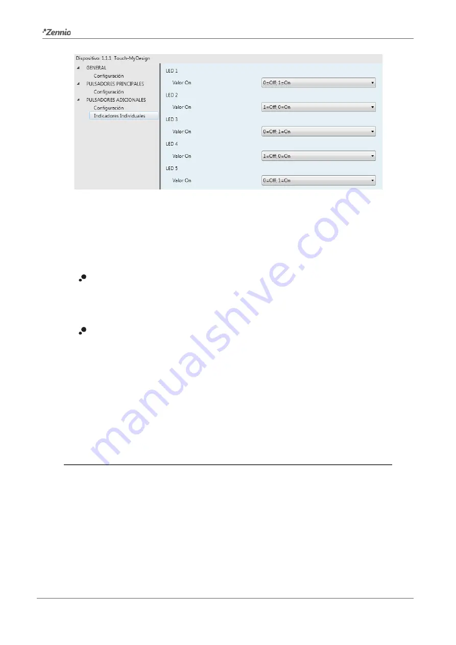
Figure 20
Individual indicators (additional buttons)
One parameter named “ON Value” will be shown for each of the five LEDs, making it
possible to associate a certain logic state (“0” ó “1”) to each light state of the LEDs (on
and off). The options available for this parameter are:
0=Off; 1=On
: the LED will switch to the “on” state (default or customized; see
“LED Lighting” in Section 3.2) when the “[Zi] LED On/Off” object receives the value
“1”, and will switch to the “off” state when it receives the value “0”.
1=Off; 0=On
: the LED will switch to the “on” state (default or customized; see
LED lighting in Section 3.2) when the “[Zi] LED On/Off” object receives the value
“0”, and will switch to the “off” state (default or customized) when it receives the
value “1”.
It is possible to link (via group addresses) the “[Zi] LED On/Off” objects to objects from
other devices in the domotic environment, thus making the LEDs of the additional
button panel act as indicators of the current state of those objects at any time.
3.5
INPUTS
The “Inputs” tab, displayed upon the enablement of such function from General
> Configuration, permits setting the required parameters for using up to two input
devices (push buttons, switches/sensors, temperature probes or movement detectors)
connected to Touch-MyDesign through the corresponding input clamp.


