background image

Page 12 

TO GET ASSISTANCE, CALL: 919-774-7667 

ZENITH PUMPS 

2. Connect DC Motor Cable (cont’d) 

• 

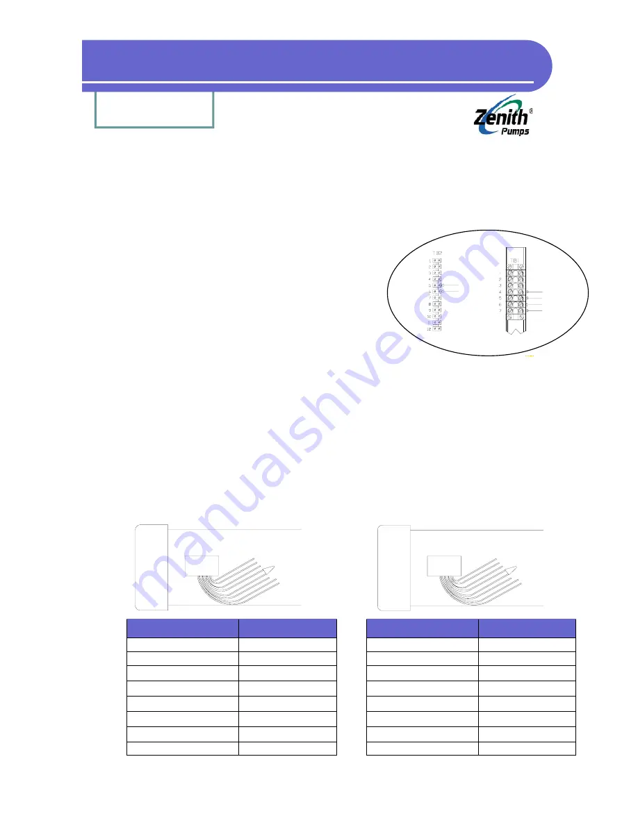
Field Wound DC Motors


Field wound motor has connections 
for its armature and field. Its armature 

connections will be labeled A1 and 
A2. Its field will have 4 wires.  

Select your motor from the connection 
diagrams below. 


NOTE:  

− 

Always refer to pump drawing 
for correct pump rotation. To change rotation, reverse A1 and A2 connections


− 

The motor connections shown above will produce a counter-clockwise rotation 
at the reducer output shaft, viewed from the pump end (as opposed to the motor 

end). This rotation should be correct for most applications. If the rotation is in-
correct, reverse A1 and A2 connections 

− 

If the motor in use has a thermostat, it may be connected to TB2-5 and TB2-6, 
after removing the jumper


Field Wiring (cont’d) 

Motor A2 

Motor A1 
Motor F1 

Motor F2 

Motor 

Thermostat 
Wires 

2 HP Explosion Proof Motors 

(Reliance) 

1 HP Explosion Proof Motors 

(Baldor) 

Wire Label 

Connect With 

A1 

TB1-5 (A1) 

A2 

TB1-4 (A2) 

F1 

TB1-6 (F1) 

F2 

Short with F11 

F11 

Short with F2 

F22 

TB1-7 (F2) 

P1 Thermostat 

TB2-5 (Thermostat) 

P2 Thermostat 

TB2-6 (Thermostat) 

Wire Label 

Connect With 

A1 

TB1-5 (A1) 

A2 

TB1-4 (A2) 

F1 

TB1-6 (F1) 

F2 

Short with F3 

F3 

Short with F2 

F4 

TB1-7 (F2) 

J Thermostat 

TB2-5 (Thermostat) 

J Thermostat 

TB2-6 (Thermostat) 

Содержание ZeDrive

Страница 1: ...derutilized and idle equipment along with credit for buybacks and trade ins Custom engineering so your equipment works exactly as you specify Critical and expedited services Leasing Rentals Demos In s...

Страница 2: ...CODE DESCRIPTION CODE DESCRIPTION CODE DESCRIPTION 1 PRI SETPT 1 16 ACCEL RATE 40 TACH 2 PRI SETPT 2 17 DECEL RATE 41 EXTERNAL REF 3 SEC SETPT 1 61 CTRL PRI 42 AUX INPUT 4 SEC SETPT 2 62 CTRL SEC 43 F...

Страница 3: ...etpoint 26 Feedback Control by Using a Flowmeter with Frequency Signal 27 Feedback Control by Using a Flowmeter with 4 20 mA Signal 29 Feedback Control by Using a Flowmeter with 0 10 VDC Signal 30 Mas...

Страница 4: ...ation cont d Replaced Feedback Sensor Fits the Existing ZeDrive Or Not 41 Display Shows 1 2 or 3 41 Restore Back to Factory Defaults 41 Can Not Operate from Keypad 42 The Display Would Not Light Up 42...

Страница 5: ...ve can receive three frequency inputs supporting magnetic pickup zero crossing or open col lector type sensor It comes standard with a RS 485 as well as a RS 422 computer interface allowing to monitor...

Страница 6: ...in Reset and Rate Scaling Format Master Follower Offset Direct Keypad Controls Set Speed Tach Display Numeric Keys Up Down Buttons Serial Communication RS 422 Full parameter access control Protection...

Страница 7: ...14 15 16 17 Feedback Sensor Ext Ref Sensor Offset Sensor JOG R STOP RUN F STOP Spare Closed Open Loop Ramp Disable Primary Setpt 2 Primary Setpt 1 Keypad Lockout Primary Secondary Secondary Setpt 3 Se...

Страница 8: ...rive from the panel front and slide it in until it is flush with the panel surface Ensure that supplied gasket is between the drive bezel and panel surface Re install the locking cam fasteners from th...

Страница 9: ...onduit from low voltage 50 V or signal wiring If run parallel to each other high voltage wiring should be separated from low voltage and signal wiring by 12 inches or as much as physically possible If...

Страница 10: ...Page 9 TO GET ASSISTANCE CALL 919 774 7667 ZENITH PUMPS Control Cabinet Wiring...

Страница 11: ...74 7667 ZENITH PUMPS 1 Connect Input Power Customer supplies input AC power NOTE Make sure to set power selection switch to correct power voltage configura tion 115 230 VAC 10 15 1 Phase 50 60 Hz 3 Wi...

Страница 12: ...ounter clockwise rotation at the reducer output shaft viewed from the pump end as opposed to the motor end This rotation should be correct for most applications If the rotation is in correct reverse A...

Страница 13: ...end as opposed to the motor end This rotation should be correct for most applications If the rotation is in correct reverse A1 and A2 connections If the motor in use has a thermostat it may be connec...

Страница 14: ...d Hall Effect Sensor Wire Color Function Connect To Red 12VDC TB2 1 White Clear Feedback Signal TB2 2 Black Common TB2 3 Bare Shielding TB2 4 Encoders Wire Color Function Connect To Red 12VDC TB2 1 Wh...

Страница 15: ...al feedback signal in engineering unit Scroll Buttons To increase decrease the value showing in LED display CLEAR To erase value in LED display or code number under code select mode ENTER To enter new...

Страница 16: ...Value Select Code View Its Value Tach Display Modify Value SET SPEED 6 0 Previous Display Current Set Speed CODE SELECT ENTER 1 Or Enter New Set Speed New Set Speed TACH Previous Display Actual Speed...

Страница 17: ...Alarm output is energized 13 High Alarm 1800 Motor speed level which High Alarm output is energized 16 Acceleration Time 10 Seconds for motor to increase from 0 RPM to 1800 RPM 17 Deceleration Time 5...

Страница 18: ...Page 17 TO GET ASSISTANCE CALL 919 774 7667 ZENITH PUMPS Typical Applications Solutions...

Страница 19: ...rive If the power is 230 VAC please refer to Trouble shooting section 4 Configure ZeDrive A 5 091 1 reducer and 120 teeth pickup gear is used for the following example Change values for codes 20 22 an...

Страница 20: ...Please refer to Trouble shooting sec tion If the system runs at right speed stop the system and discon nect the power The system is ready for normal operation Zenith Pumps SET SPEED TACH 7 4 1 8 5 2...

Страница 21: ...p based on Accel eration Time defined in Code 16 2 Stop Button Use a momentary button Connect the button to J3 connector Pin 11 and Pin 12 When opened ZeDrive will ramp down to zero speed based on Dec...

Страница 22: ...rectly coupled with the motor the gear ratio R 1 Motor maximum speed VM RPM 2 Calculation None 3 Coding Check and change the following codes Code 10 0 Code 11 VM Code 20 VM R Code 22 VM R Code 34 VM C...

Страница 23: ...with the motor the gear ratio R 1 Motor maximum speed VM RPM Pump Capacity CP cc rev 2 Calculation None 3 Coding Check and change the following codes Code 10 0 Code 11 VM Code 20 VM R CP Code 22 VM R...

Страница 24: ...ent between other unit and cc min KU Find out 1 new volume unit is equal to V cc Find out 1 new time unit is equal to T min 1 volume time V cc T min V T cc min KU V T Example If the preferred unit is...

Страница 25: ...n at the left 2 Calculation None 3 Coding Check and change the following codes Code 80 input corresponding code number for monitoring that specific variable Example Code 80 40 it will monitor TACH whi...

Страница 26: ...eeth of Feedback Gear N 120 for most of systems supplied by Zenith 2 Calculation To set the motor speed to be V RPM 0 V VM the pump to be V RPM 0 R V VM R or the output to be V cc min 0 R CP V VM R CP...

Страница 27: ...eeth of Feedback Gear N 120 for most of systems supplied by Zenith 2 Calculation To set the motor speed to be V RPM 0 V VM the pump to be V RPM 0 R V VM R or the output to be V cc min 0 R CP V VM R CP...

Страница 28: ...For ZeDrive 2000 please proceed to the next step For a regular ZeDrive check and change the jumper settings on the Control Board 1 Loosen up 6 screws on the back panel and 2 screws located on the heat...

Страница 29: ...gested speed limit Any restriction at the discharge side of the pump can rapidly increase the speed of pump This is the major causation making the pump over speed Check any down stream restrictions be...

Страница 30: ...the wires from the flowmeter as shown at left Leave anything else unchanged as before 5 Result The output from the pump will be controlled by the flowmeter The units of the setpoint and the Tach are...

Страница 31: ...e wires from the flowmeter as shown at left Leave anything else unchanged as before 5 Result The output from the pump will be controlled by the flowmeter The units of the setpoint and the Tach are sam...

Страница 32: ...ck Sensor Resolution Ff No of Teeth 2 Calculation 2 1 Master Primary Setpoint Pm cc min Pm cc min VM RPM Rm Cm cc rev 2 2 Maximum Percent between Follower and Master Pf Pf Follower Max Flowrate cc min...

Страница 33: ...are wire shield wire Connect wires like the following illustration to form a master follower system for detailed connection please refer to page G 4 in ZeDrive and ZeTrol Manual Follower ZeDrive 1 2 3...

Страница 34: ...rimary Setpoint 1 Code 01 i e 20 cc min The master system should run and the follower system should run and deliver 75 the flowrate the master system delivers Stop the master system the follower will...

Страница 35: ...2 Neutral 2 2 Turn the current limit potentiometer at the rear of ZeDrive fully clockwise 2 3 With ZeDrive in the RUN state gradually in crease the load until the AC ammeter reaches the desired limit...

Страница 36: ...DC or 4 20 mA calibration signal to ZeDrive Locate Analog Select Jumpers on Control Board 1 Loosen up 6 screws on the back panel and 2 screws located on the heat sink of ZeDrive 2 Remove the back pane...

Страница 37: ...e a multi meter Locate Analog Select Jumpers on Control Board 1 Loosen up 6 screws on the back panel and 2 screws located on the heat sink of ZeDrive 2 Remove the back panel place ZeDrive as shown at...

Страница 38: ...Page 37 TO GET ASSISTANCE CALL 919 774 7667 ZENITH PUMPS Trouble shooting Fault Information...

Страница 39: ...If the voltage always stay at 0 VDC or any value below 1 VDC please check the sensor wiring If the wiring is correct it may be a defected sensor Please contact Zenith for a re placed one If the voltag...

Страница 40: ...of sensor you have please check the feedback jumper settings as shown at the left 3 System Always Runs at Full Speed Refer to 2 No Feedback Signal 4 System Can Not Run Below 30 RPM or 40 RPM Refer to...

Страница 41: ...eck Code 16 for acceleration time Smaller the value lesser the time for the motor to ramp up However it may increase the chance to damage the pump due to the quick pressure build up caused by the rest...

Страница 42: ...k panel and 2 screws located on the heat sink of ZeDrive 2 Remove the back panel Face the back of Ze Drive and place ZeDrive so that the heat sink points down 3 When you place ZeDrive as shown in step...

Страница 43: ...fault values The defaults may NOT match the actual system you have 18 Can Not Operate from Keypad ZeDrive could be set for Analog Remote Control mode To use keypad on ZeDrive to control the system set...

Страница 44: ...LIMIT alarm LED lights up This parameter establishes the point at which the LO ALARM output is turned on 13 LIMIT alarm LED lights up This parameter establishes the point at which the HI ALARM output...

Страница 45: ...Page 44 TO GET ASSISTANCE CALL 919 774 7667 ZENITH PUMPS Complete Code List...

Страница 46: ...mat Multiplier ratio Offset output format Multiplier ratio This parameter establishes the speed at which the motor rotates during a JOG operation It is always measured at the drive motor shaft This pa...

Страница 47: ...C15 the alarm is turned on This parameter establishes the maximum level of motor RPM during operation It is allowable to program a setpoint which is above this value however the controller will enfor...

Страница 48: ...ized feedback pulses minus the Feedback pulses It may not always be desirable to recover all the position error lag Set this paramter to the desired lag pulse limit It sets a maximum pulse error count...

Страница 49: ...hed to External Reference Input for each revolution of its shaft It is the number of pulses per revolution generated by the device attached to Motor Shaft It is the number of pulses generated by the d...

Страница 50: ...Reference and is used in Follower or Offset formats when the primary data set is selected It sets the full scale speed of the motor When the motor is turning at this speed with a primary setpoint sel...

Страница 51: ...larger than 9999 When this occurs the value is displayed differently For example a 10 00 display indicates 10 000 Hz It is the feedback displayed in scaled Engineering Units The feedback input is rea...

Страница 52: ...le than Tachometer display due to sensor irregularities or other system dynamic errors It may contain numbers larger than 9999 When this occurs the value is displayed differently For example a 10 00 d...

Страница 53: ...the forward reverse flag on ZeTrol Bit 5 Closed Loop 1 Open Loop 0 Bit 4 Primary Setpoint 1 1 Primary Setpoint 2 0 Bit 3 Secondary Setpoint 3 1 Secondary Setpoint 4 0 Bit 2 Local 1 Remote Serial 0 Con...

Страница 54: ...Primary Scaling Format Default 1 62 Secondary Scaling Format Default 1 Units Range 0 Direct 1 Master 2 Follower 3 Offset It is Analog Input 1 signal unadjusted for Zero and Span It is Analog Input 1 s...

Страница 55: ...smaller numbers mean more Gain This parameter sets Reset in PID control loop This is the integral part I of the equation It is an integer number between 0 and 9999 with 0 being the special case of no...

Страница 56: ...y Setpoint Select 1 Bit 3 Secondary Setpoint Select 1 Bit 2 Run 1 Stop 0 Bit 1 Bit 0 Ramp Enable 1 Disable 0 This parameter sets a threshold below which the Rate term derivative term has no affect on...

Страница 57: ...he Analog Output pins These are positive and negative offset numbers for primary and secondary data sets These allow the feedback to contain a bias Only one positive or negative number can be non zero...

Страница 58: ...ace Setpoint 2 6 Replace Setpoint 3 7 Replace Setpoint 4 85 Analog Input ZERO Default 0 Units Range 0 2048 86 Analog Input SPAN Default 3900 Units Range 2048 4096 It allows user to zero adjust the ana...

Страница 59: ...Page 58 TO GET ASSISTANCE CALL 919 774 7667 ZENITH PUMPS System Drawings...

Страница 60: ...SIGNAL INTER LOCK ANALOG INPUT ANALOG OUTPUT 12 VDC SIGNAL COMMON SHIELD ROMOVE JUMPER INPUT COMMON OUTPUT SHIELD J 2 J 1 J 3 J 4 NOTES 1 FOR INTERCONNECT WIRING BETWEEN ZeDRIVE AND TERMINAL STRIPS R...

Страница 61: ...Y THE OPPOSITE END OF THE SHIELD IS NOT CONNECTED 2 ROUTE SHIELDED CABLE SEPARATELY FROM POWER WIRING DO NOT ROUTE 115VAC CONTROL WIRING AND LOW LEVEL SIGNAL WIRING IN THE SAME CONDUIT DO NOT ROUTE FE...

Страница 62: ...TB1 4 TO TB1 4 MOTOR END W COVER REMOVED TO TB1 5 CASE GROUND TO TB1 3 TO TB1 4 FIELD WOUND MOTORS TO TB1 5 1 2 HP EXPLOSION PROOF MOTORS TO TB1 4 TO TB1 5 NOTES 1 THE MOTOR CONNECTIONS SHOWN WILL PR...

Страница 63: ...Phone 800 277 8968 Fax 919 774 5952 E mail zenithpumps zenithpumps com Zenith Pumps 5910 Elwin Buchanan Drive Sanford NC 27330 ZENITH PUMPS Zenith Pumps...

Страница 64: ...uipment Have surplus equipment taking up shelf space We ll give it a new home Learn more Visit us at artisantg com for more info on price quotes drivers technical specifications manuals and documentat...

Отзывы: