background image


Instrument Description  

000000-1253-546  VISUCAM C   31.07.2003 

15

Start-up 

Installation 

As a rule, the following operations are carried out by the user. 

❏ 

Remove and unpack the accessory cardboard box (keyboard, mouse, 
etc.). 

❏ 

Remove the instrument from the cardboard box at the plastic taut 
strap. 

❏ 

Remove the taut strap and plastic foam pads. 

❏ 

Place the instrument on the table (handle it carefully; do not lift or 
carry the instrument at the camera head!). 

❏ 

Remove the plastic-foam transport locks. 

❏ 

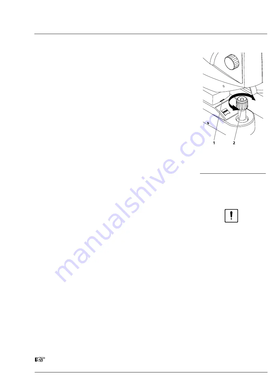
To remove the red transport fixation plate, loosen the knurled knob 
(

4

, Fig. 2) and turn the joystick (

2

, Fig. 7) clockwise until the mark 

for the center position of the height adjustment becomes visible 
(

1

, Fig. 7) 

❏ 

Then pull out the plate from the patient side. 

❏ 

If used, plug the fixation lamp into the corresponding mount and 
lock it by means of sleeve nut (

1

,  Fig. 3). 


Electrical connection 

Caution 

Before establishing electrical connections, make sure the power plugs 
on basic unit and power isolation transformer have been disconnected. 
 

• 

Connect the cable of the camera head (DEVICE) to the connector 
panel (

5

, Fig. 4) and tighten the two screws. 

• 

Connect the monitor cable (VGA) to the connector panel (

3

, Fig. 4) 

of the VISUCAM C. 

• 

Connect the optional printer to a free USB port of the connector 
panel (

4

, Fig. 4) of the VISUCAM C. 

• 

Connect the keyboard and mouse to the connector panel (

and 

7

Fig. 4). 

• 

Connect the cable of the USB Flash Drive to a free USB port of the 
connector panel (

4

, Fig. 4) of the VISUCAM C. 

• 

Connect the power cables of monitor and printer to the power 
isolation transformer (see Fig. 6). 

• 

Connect the basic unit via power connector  (

2

, Fig. 4) and the 

power isolation transformer via power connector (

1

, Fig. 5) to 

separate permanently installed mains power outlets. 

The VISUCAM C is switched on by the power switch (

1

, Fig. 4) located 

on the connector panel).  


The external units printer and monitor are connected and switched on 
via the power isolation transformer. 

 Note 

Please also see the monitor instruction manual. 


1

Mark for center position 

2

Joystick 

Fig. 7 

Height adjustment  

instrument base 


Содержание VISUCAM C

Страница 1: ...VISUCAM C DigitalCamera Gebrauchsanweisung User s Manual Mode d emploi Instrucciones de uso...

Страница 2: ...2...

Страница 3: ...erning the safe operation of the instrument The specifications are subject to change the manual is not covered by an update service Unless expressly authorized forwarding and duplication of this docum...

Страница 4: ...k of Microsoft Corporation Inc In general other brand names as well as names of software and hardware products are subject to trademark or patent protection Quoting of product names is for information...

Страница 5: ...he VISUCAM C 13 Power isolation transformer for external devices 14 Start up 15 Installation 15 Electrical connection 15 Optional accessories 17 Printer 17 Fixation device 17 Demonstration eye with ho...

Страница 6: ...43 RED images 44 Presentation of images 45 Image comparison and image correction 46 Printing images 49 Printing from the Patient Manager mode 49 Export of image data 51 Import export patient list 53...

Страница 7: ...r positions of warning and information signs Warning Correct operation of the VISUCAM C Digital Camera is imperative for its safe function Therefore please read these operating instructions thoroughly...

Страница 8: ...r patient and instrument Interruptions may not be made intentionally If the earthing is impaired or if any electrical leads are damaged the instrument must be taken out of service and measures taken t...

Страница 9: ...standard ISO 10940 1998 Please also keep patient exposure to a minimum during setting of the area to be examined with the infrared illumination While no acute optical radiation hazards have been ident...

Страница 10: ...threshold values as laid down in DIN EN ISO 15004 Ophthalmic Instruments Basic requirements and testing methods are not exceeded Data backup Storing your image data on the hard disk is no substitute...

Страница 11: ...nd mount for fixation lamp 4 Monitor for observation of patient eye and display of instrument specific information 5 USB Flash Drive optional accessory 6 Keyboard and mouse for the entry of patient da...

Страница 12: ...Instrument Description 000000 1253 546 VISUCAM C 31 07 2003 10 Controls of the VISUCAM C Fig 2 Controls of the VISUCAM C view from the right 3 2 5 6 4 8 10 11 1 9 7...

Страница 13: ...accessory 3 Fastening pins for paper pads 4 Knurled knob for locking the instrument base 5 Mouse 6 Keyboard 7 Connector panel 8 Control for adjusting the brightness of the halogen lamp 9 Joystick for...

Страница 14: ...Instrument Description 000000 1253 546 VISUCAM C 31 07 2003 12 Fig 3 Controls of the VISUCAM C view from the left 1 2 5 6 3 4 8 7 9 10...

Страница 15: ...Software package Software version Windows license Connector panel of the VISUCAM C Fig 4 Connector panel Fig 4 shows the connector panel 1 Power switch 2 Power cable 3 Monitor VGA 4 2x USB port prefe...

Страница 16: ...strument table Non compliance presents a violation of the regulations for the use of medical devices as per DIN EN 60601 1 1 If you use the IT 3L or IT 2S Instrument Table from Carl Zeiss for the VISU...

Страница 17: ...ower plugs on basic unit and power isolation transformer have been disconnected Connect the cable of the camera head DEVICE to the connector panel 5 Fig 4 and tighten the two screws Connect the monito...

Страница 18: ...able connections must be properly secured with cable clamps and laid in the cable ducts provided Also use the VISUCAM C connection diagram enclosed to connect the system components After switch on at...

Страница 19: ...essibly by moving the control handle To install the fixation device unscrew the stopper and replace it by the internal fixation device Demonstration eye with holder The demonstration eye is designed f...

Страница 20: ...quired Operation is easy and quickly learned by the user Camera adjustment freedom from reflections image sharpness has to be assessed on the monitor When capturing images the set image displayed on t...

Страница 21: ...click etc The program includes only a few forced procedures The user can switch back and forth between the two Patient Manager and Image Capture desktops In rare cases it may occur that Windows error...

Страница 22: ...s OK confirmation activation Double click Reduction enlargement of survey window used as positioning aid Reduction enlargement of thumbnails Dragging the mouse while holding the left mouse button depr...

Страница 23: ...n access all patient related information such as patient list available visits with captured images image comparison and image correction and activate image export and import as well as print preview...

Страница 24: ...ure desktop 1 Menu bar at top edge of the window 2 Toolbar with icons directly below the menu bar 3 Function buttons on Patient Manager desktop and function buttons and large display field for image p...

Страница 25: ...line help Image capture Export patient list About Opens Image Capture desktop Opens dialog for exporting patient data Opens information window about the program version etc Printer settings Format CD...

Страница 26: ...desktop Requires previous selection of a patient Opens the image comparison and correction dialog box The preview shows all selected images Opens the Print Preview window The preview shows all selecte...

Страница 27: ...ialog box for the entry of a new patient 2 Button for opening the Patient dialog box for editing existing patient data 3 Patient display field 4 Button for transferring a patient to the Waiting Room 5...

Страница 28: ...ined letter 1 Single Image or Video Clips selector buttons 2 Capture mode selector buttons COLOR GREEN RED 3 Button for activating the IR observation 4 Selector buttons for image angles 45 and 25 5 Di...

Страница 29: ...d for selected light pulse 13 Button 9 for changing the light pulse start value only available when the check box Enable definition of startup pulse levels is activated see program settings Capture pa...

Страница 30: ...ser Only the Windows Control Panel functions shown in Fig 15 are accessible via the menu command File System Opening of the System dialog box requires the entry of a password Afterwards you can activa...

Страница 31: ...t Export Image Capture Printing In the General Information Patient Information and Logo fields choose the information that shall appear on the printout by activating the corresponding check boxes Chan...

Страница 32: ...he printout if selected on the Printing tab or exported along with image export in DICOM format Click on the respective textbox and type in the desired data via the PC keyboard Confirm your entries by...

Страница 33: ...and Feel and confirmation of deletion If you want to have the overview images of a selected visit displayed also in the Image Capture desktop activate the View earlier images in capture mode check bo...

Страница 34: ...folder to immediately recognize whether the desired patient data are already available in the folder Enter the desired value in seconds in the text box Request frequency in s Click the text box Standa...

Страница 35: ...me stamp on captured images Automatic image enhancement Enable changing the light pulse start values Translucency of the mask of the image section Extended user interface Activate the desired display...

Страница 36: ...levels check box The respective button is then displayed on the Image Capture desktop To use the SNAP function see Fig 13 activate the Advanced User Interface Confirm your entries by a click on the O...

Страница 37: ...the eye level Adjust the instrument Position the instrument to the eye free of reflections Focus the image Trigger image capture Image display image comparison image correction 1 Fast image display C...

Страница 38: ...name first name date of birth Click on the Name textbox and type in the patient name Use the Tab key or the mouse to activate the First name textbox and type the patient s first name Move to the next...

Страница 39: ...ing Room by a mouse click On selection of the patient the corresponding visits of the patient if available will appear in the Patients display field Click on the visit of interest The images captured...

Страница 40: ...n of the mode all other options active sensor filter setting light pulse will be set by the program You can customize these settings if necessary If you want to customize the VISUCAM C for infrared im...

Страница 41: ...or the set capture mode just click on the button 9 below the displayed pulse value once see 13 Fig 13 This new start value is then always defaulted when the software is restarted Note The button 9 is...

Страница 42: ...atient look either with the non examined eye to the external fixation light or with the eye to be examined to the target of the internal fixation device Turn lamp brightness control 8 Fig 2 on instrum...

Страница 43: ...rd so that forehead and chin are firmly positioned Adjust your seat if necessary Note Since reflections cannot be judged correctly in infrared light the position and focus of the light ring is immense...

Страница 44: ...ction are sharp Correct the position of the instrument keeping the same distance from the eye very important until the reflection disappears from the visible image Pull back the VISUCAM C about 1 mm f...

Страница 45: ...is included in the comment of image capture OS OD Color images COLOR In COLOR mode the patient eye is captured in true colors Activate the COLOR mode by a click on the corresponding button on the Ima...

Страница 46: ...corresponding button on the Image Capture desktop The necessary parameters such as filter and light pulse intensity will be set automatically Release image capture by pressing the pushbutton on the jo...

Страница 47: ...been printed IMAGE EXPORT icon if image has already been exported COPY icon if the image has been re saved For a quick view of a specific image follow this procedure Choose patient visit Double click...

Страница 48: ...as follows In thumbnail view choose the desired images by mouse clicks and with the CTRL or SHIFT key depressed Click the IMAGE COMPARISON AND CORRECTION button to open the Image comparison and corre...

Страница 49: ...t by clicking with the left or right mouse button Adjusting the brightness Activate the Brightness icon Position the mouse pointer on the image content and increase or reduce the brightness by clickin...

Страница 50: ...on the Add image to printing layout icon The image is added to the printing layout Icon is only available when the 1 image 2 images 4 images tab is activated and when images have been removed from th...

Страница 51: ...o check your choice before printing click on the PRINT PREVIEW icon To start the printout click the PRINT button Note It is advisable not to print until you have quit the capture mode For the customiz...

Страница 52: ...an four images it is advisable to use the mode 4 images to correct the images Remove any images you do not need for the printout with the Remove image from printing layout function Rearrange the image...

Страница 53: ...data loss Note When viewing exported video clips in AVI format on computers with an older operating system it may happen that the video clips cannot be displayed In this case you have to install a su...

Страница 54: ...D RW to format the CD Note Formatting of a CD RW takes approx 20 to 30 minutes Please note that during formatting you cannot write data to the CD RW or capture images To eject the formatted CD RW use...

Страница 55: ...the network see Fig 20 For the import of patient data you can use any text file format Use the list separator displayed in the Settings Import Export dialog box see page 32 Strictly keep the followin...

Страница 56: ...ick on textbox or the calendar click on arrow beside the list box Note If you do not activate any of the Delete Options no images will be deleted Confirm your choice by a click on the CONTINUE button...

Страница 57: ...ring will also forfeit any rights to claim under warranty The maintenance work you may carry out yourself is described below Please use original Zeiss components only Note To restart the system after...

Страница 58: ...new lamp with bare fingers as this will reduce light intensity Changing the halogen lampe 1 2 3 1 8 V 20 W halogen lamp 2 Lamp socket with lamp cable 3 Holder for halogen lamp Fig 32 Changing the lamp...

Страница 59: ...not needed only use original lamps Before reconnecting the power cable attach the cover to close the housing Replacing the blinking diode of the fixation lamp 1 2 1 Blinking diode 2 Holder of the blin...

Страница 60: ...olation transformer Open lid 1 Fig 34 located underneath the power connector Remove fuse insert 3 Fig 34 with fuse by slightly depressing snap in clip 4 Fig 34 at the inside of the fuse insert Replace...

Страница 61: ...ng regulations must be observed for selecting the suitable disinfectant and method of disinfecting We recommend the use of ethanol DAB 10 80 vol or isopropanol 70 vol for disinfecting the used parts N...

Страница 62: ...essage Cable not connected on monitor Signal cable of monitor not connected to basic unit Connect monitor signal cable to basic unit Lamp voltage control adjusted to Minimum Turn control clockwise unt...

Страница 63: ...er isolation transformer fuses 2 x T3 15 A H 250 V 5x20 IEC 60127 2 V Technical Data Ambient conditions for intended use Temperatur 10 35 C 50 95 F Rel humidity 30 75 Air pressure 800 1060 hPa Storage...

Страница 64: ...t in form of the German Medical Product Act MPA Device Class as per MPA I UMDNS No 12 815 DICOM Conformance Statement The manufacturer supports the export of images in the file format in conformance w...

Страница 65: ...tings 28 Connector panel 13 Controls 10 19 20 D Demonstration eye 17 Design 9 Desktop 19 Image Capture 21 26 Patient Manager 21 25 DICOM 18 51 62 Disposal 59 E Electrical connection 15 Export 32 F Fix...

Страница 66: ...solation transformer 14 Preparation 36 Presentation 45 Printing 29 49 Program control 19 Program control buttons 25 26 Q Quit Program 54 R RED images 44 Replacing the fuse 58 S Safety Notes 5 Screen l...

Страница 67: ......

Страница 68: ...AG Goeschwitzer Str 51 52 D 07745 Jena Germany Phone 49 3641 220 333 Fax 49 3641 220 282 Email info meditec zeiss com Internet www meditec zeiss com 000000 1253 546 VISUCAM C 31 07 2003 Specifications...

Отзывы: