background image

YZ Systems Milton Roy • 201 Ivyland Road • Ivyland, Pennsylvania • USA • 18974 • P: 281.362.6500 • www.yzsystems.com

Page II 

NJEX 7300G  ver.08-2018

7300G Table of Contents

Section 5:  Programming for Proportional-to-Flow Operation ....................................................

25

Setting Operator Input Parameters

....................................................................................................

25

Odorant injection rate in lbs/MMCF (mg/m3) of gas ..........................................................................

25

Pump displacement in cc/stroke ........................................................................................................

25

Odorant density in lbs/gallon (g/cc) @ 60º F .....................................................................................

25

Max gas flow in MMCF/Hour (m3/sec) ..............................................................................................

26

Low Flow Shut Off .............................................................................................................................

26

Flow (no signal) input ........................................................................................................................

26

Maximum Time/Stroke .......................................................................................................................

27

The Odorant Output Setting ..............................................................................................................

27

Odorant Tank .....................................................................................................................................

28

Expansion Tank Pressure Monitoring  ...............................................................................................

28

Odorant Inlet Pressure Monitoring 

....................................................................................................

29

Alarm to Relay Delay  ........................................................................................................................

30

Alarm to Call Out Delay  ....................................................................................................................

30

MODBUS Address  ............................................................................................................................

30

MODBUS Parameters  ......................................................................................................................

31

Conclusion .........................................................................................................................................

31

Section 6:  Programming for Proportional-to-Time Operation ....................................................

33

Setting Operator Input Parameters

....................................................................................................

33

Pump displacement in cc/stroke ........................................................................................................

33

Odorant density in lbs/gallon (g/cc.) @ 60ºF .....................................................................................

33

Time interval between strokes of the pump in xx.xx minutes/stroke: ................................................

33

The Odorant Output Setting   ............................................................................................................

34

Odorant Tank .....................................................................................................................................

34

Expansion Tank Pressure Monitoring  ...............................................................................................

35

Odorant Inlet Pressure Monitoring

.....................................................................................................

35

Alarm to Relay Delay  ........................................................................................................................

36

Alarm to Call Out Delay  ....................................................................................................................

36

MODBUS Address  ............................................................................................................................

37

MODBUS Parameters  ......................................................................................................................

37

Conclusion .........................................................................................................................................

38

Section 7:  Calibrating Signal Inputs .............................................................................................

39

Analog Flow Input Calibration, 1-5 VDC / 4-20 mA ...........................................................................

39

Expansion Tank Pressure Transmitter Zero Calibration ....................................................................

41

Odorant Inlet Pressure Transmitter Zero Calibration .........................................................................

42

Pulse Flow Input Calibration, Dry Contact & Voltage Pulse ..............................................................

44

Calculation for Determining the Span Frequency Example ...............................................................

45

Содержание NJEX 7300G

Страница 1: ...NJEX 7300G N A T U R A L G A S O D O R I Z A T I O N S Y S T E M ...

Страница 2: ......

Страница 3: ...The NJEX 7300G Instruction Operating Manual Version 08 2018 ...

Страница 4: ......

Страница 5: ...ation 5 Standard System Components 5 System Flow Schematic 6 Standard System Mounting 7 Standard System Connections 8 Skid System Components 10 System Flow Schematic 12 Skid System Mounting 13 Skid System Connections 15 Section 3 Filling the Bulk Odorant Tank 17 Filling the Tank for the First Time 17 Refilling the Bulk Odorant Tank 18 Section 4 System Control Electronics 19 Overview 19 To Use The ...

Страница 6: ...Out Delay 30 MODBUS Address 30 MODBUS Parameters 31 Conclusion 31 Section 6 Programming for Proportional to Time Operation 33 Setting Operator Input Parameters 33 Pump displacement in cc stroke 33 Odorant density in lbs gallon g cc 60ºF 33 Time interval between strokes of the pump in xx xx minutes stroke 33 The Odorant Output Setting 34 Odorant Tank 34 Expansion Tank Pressure Monitoring 35 Odorant...

Страница 7: ...ltage 50 Battery Alarm 50 Flow Input 50 Flow Input Alarms 50 Flow Input Indicators non alarm 50 Tank Level 51 Tank Level Alarm 51 Odorant Temperature 51 Section 9 Setting Testing Alarms 53 Setting Alarm Out Status 53 Testing Alarm Out Status 55 Setting The Clock 58 Section 10 Mechanical System 61 Overview 61 Odorant Inlet Manifold Bulk Odorant Filter Assembly 62 Fill Valve 62 Verometer 63 Model 70...

Страница 8: ...larm Non Alarm Indicator Troubleshooting Steps 85 Loss of Flow Alarm Troubleshooting Steps 85 Overflow Alarm Troubleshooting Steps 85 Low Flow Non Alarm Indicator Troubleshooting Steps 86 Overflow Non Alarm Indicator Troubleshooting Steps 86 Verometer Alarms 86 Verometer Non Alarm Indicators 87 Verometer Troubleshooting Steps 87 Verometer Cable Alarm Troubleshooting Steps 87 Verometer No Fill Alar...

Страница 9: ...ve Assembly Exploded View 98 Fill Valve Exploded View 99 VM 1100 Verometer with Filter Assembly Exploded View 100 Bulk Odorant Filter 101 NJEX Gas Filter 102 Electronics Assembly 103 SPS 12 Solar Power Supply Unit 104 LPS 120 240 Charger Supply Unit 105 Heater Wiring Diagram 106 Appendix B N 300 Modbus Specifications 107 Communications Settings 107 N300 Modbus Function Support 107 Boolean Register...

Страница 10: ......

Страница 11: ...will begin discussing the in depth opera tion of the N 300 electronic controller where many of these typographic conventions will be found In the discussion about the controller the technician will learn about the dual use keypad Here the controller LCD will display a new function for the key located im mediately below the displayed item For example an Up Arrow key may have Set immediately above i...

Страница 12: ...condition ing of the actuation gas supply may be required Where the actuation gas supply has a high water content and or a low hydrocarbon dew point addition al actuation gas filtration or heating of the actuation gas supply may be necessary Bottled nitrogen can also be used during cold operating conditions to avoid condensation in the actuation gas supply line In addi tion operation at extreme te...

Страница 13: ...ation and a loss of flow input signal For systems with analog inputs if a loss of flow signal occurs the controller automatically defaults back to a pre selected percentage of the flow input The flow input signal is read by the N 300G controller eight times per pump stroke These readings are aver aged and the time duration until the next stroke is then calculated by the controller The maximum time...

Страница 14: ...YZ Systems Milton Roy 201 Ivyland Road Ivyland Pennsylvania USA 18974 P 281 362 6500 www yzsystems com Page 4 NJEX 7300G ver 08 2018 Section 1 First Things To Know About The 7300G Notes ...

Страница 15: ...orage tank and the NJEX 7300G The Bulk Odorant Filter is pre installed inside the System Enclosure attachment to the odorant source is via an odorant inlet manifold equipped with 1 4 FNPT connection located on the back of the System Enclosure Service Tray Not Illustrated should be installed in the bottom of the system enclosure to capture any drops that may occur during servicing of the odor izer ...

Страница 16: ...YZ Systems Milton Roy 201 Ivyland Road Ivyland Pennsylvania USA 18974 P 281 362 6500 www yzsystems com Page 6 NJEX 7300G ver 08 2018 Section 2 System Installation System Flow Schematic Figure 4 ...

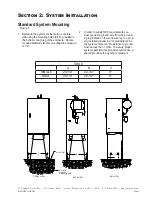
Страница 17: ... mounting holes 9 16 provided in the bottom of each leg of the enclosure Recom mended bolt stud sizes for mounting the enclosure is 1 2 2 In order to satisfy NEC requirements you must connect a ground wire from the ground ing lug located on the enclosure leg to a prop erly installed ground rod located adjacent to the system enclosure Resistance to ground must be less than 1 Ohm To assure proper sy...

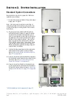
Страница 18: ...sion proof code via a termination junction box not shown to be attached to the conduit provided at the upper left side on the system enclosure The nominal power requirement for 120VAC will be 100 mA or for 240VAC will be 50mA These power inputs must be fused with a maximum of 15A figure 7 Minimum allowable operational voltage range for input is 85VAC to 250VAC 2 Connect the flow signal device to t...

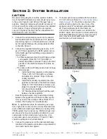
Страница 19: ... Install the secondary regulator at the inlet gas filter on the back of the NJEX enclosure Fisher 67 YZ P N A3 0042 or similar and adjust it to provide 75 psig to the NJEX Sys tem should be acceptable 3 3 8 Stainless Steel tubing should be used between the two regulators Dual Pump enclosures may require larger tubing between the regulators and the secondary regula tor may need to have a larger ori...

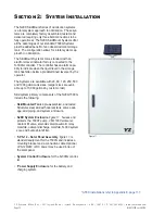
Страница 20: ...m capa bility to indicate when the liquid level in the storage tank has fallen below a predetermined level set by the operator The Systems are available with 20 60 120 250 500 and 1000 gallon tank sizes Larger sizes are avail able up to 10 000 gallons by custom order Skid system primary components of the NJEX 7300G include the following Skid Mounted Tank a pre assembled and tested Structural steel...

Страница 21: ...ystem enclosure Mechanical Interconnect Cable figure 12 pro vides the connection between the system control enclosure and the electrical components located in the mechanical section Expansion Tank figure 13 provides a closed loop system for pressure fluctuations within the Verometer during the odorant fill and injection cycle NJEX Gas Filter figure 13 installed between the actuation gas regulator ...

Страница 22: ...YZ Systems Milton Roy 201 Ivyland Road Ivyland Pennsylvania USA 18974 P 281 362 6500 www yzsystems com Page 12 NJEX 7300G ver 08 2018 Section 2 System Installation Figure 14 System Flow Schematic ...

Страница 23: ...delines a Lift containment skid systems using all four eyebolts on the corners of the skid b Lift rail skid systems from the bottom of the skid by forklift or other sup portive device c Do not move a system with liquid in the odorant tank d Do not lift a system by the tank lugs these lugs are designed only for the weight of the empty tank 3 Bolt the system to the concrete slab using the mounting h...

Страница 24: ...SYSTEMS TANK CABINET BL BW O L W WEIGHT gallons inches inches inches inches inches pounds 20 Single 50 32 8 66 36 800 Double 31 58 7 45 62 850 60 Single 56 32 8 72 36 950 Double 36 58 7 50 62 1000 120 Single 82 32 8 98 36 1200 Double 82 54 8 98 58 1350 250 Either 108 58 8 124 62 1850 500 Either 116 58 8 154 62 2600 1000 Either 192 64 8 240 68 4250 2000 Either 252 69 14 318 73 7850 ...

Страница 25: ...with explosion proof code via a termination junction box to be attached to the conduit provided at the upper left side on the system enclosure The power requirement for 120VAC will be 100mA or for 240VAC will be 50mA these power inputs must be fused with a maximum of 15A figure 7 Minimum Allowable operational voltage range for input is 85 VAC to 250 VAC 2 Connect the flow signal device to the term...

Страница 26: ...at the inlet gas filter on the back of the NJEX enclosure Fisher 67 YZ P N A3 0042 or similar and adjust it to provide 75 psig to the NJEX system should be acceptable 3 3 8 Stainless Steel tubing shuld be used between the two regulators Dual pump enclosures may require larger tubing be tween the regulators and the secondary regulator may need to have a larger orifice Fisher 64 or simiar if both pu...

Страница 27: ...Closed V10 V11 and V15 Note Gas Supply to V13 should NOT be turned on during this procedure 2 Attach inert or natural gas supply to V10 Section 3 Filling the Bulk Odorant Tank 3 To purge the tank open valve V10 to introduce inert or natural gas to the tank to begin displacing any ambient air from the empty tank Continue until pressure on the gage located directly above V13 is observed then partial...

Страница 28: ...acturer during this time If you are uncertain about any aspect of the odorant itself you should contact the manufacturer of your chemical prior to proceeding 1 Place the N 300G controller in the Standby Mode by pressing the Standby key 2 Verify correct position of valves before beginning figure 22 Open V12 Closed V10 V11 V13 V15 3 Connect a line from V11 to a flare or vapor recov ery device and op...

Страница 29: ...ppendix D Documents To Use The Key Pad The three main keys have multiple function capabili ties Each key is labeled with it s primary function used in moving through the menu they are as follows Select Enter The Select Enter Key Up Arrow Key Down Arrow Key These keys also have alternative functions These al ternative functions will be reflected in the commands proceeded by an asterisk that appear ...

Страница 30: ...r matches the verom eter tag number located at the top of the verometer assembly figures 27 28 29 Next you may have the option of accepting a set of Pre Configured operating parameters that have been programmed into the Sentry Module figure 30 This option will only come up if it has been set up in Sentry and not previously uploaded Record the version x xx number figure 31 in the For the Record For...

Страница 31: ... operator to locally inhibit the operation of the N 300G controller This creates a standby mode for the 7300G system In the event of a no flow condition in the pipeline the operator can switch the 7300G to a standby mode for extended periods of time or to temporarily suspend operation of the system for maintenance When flow is initiated once more or the maintenance has been completed the 7300G can...

Страница 32: ... the solar panel The battery is continuously monitored and an alarm signal is sent if the voltage falls below 11 0 volts During normal operation the LED located on the front of the SPS 12 will illuminate If AC power is available the solar panel can be replaced with an optional 120 240 AC DC Line Power Supply LPS figure 36 intrinsically safe barrier and an enclosure for Class I Division 1 Group C D...

Страница 33: ...o notify the computer and provide it with information Connections for Method 1 or 2 are via an RS 485 two wire connection In a safe nonhazardous area this may be connected to a RS 232 converter for interface with a SCADA system if required Method 3 utilizes two output relays One relay is for Alarm Output and provides single output commu nication to indicate some type of some alarm has occurred wit...

Страница 34: ...YZ Systems Milton Roy 201 Ivyland Road Ivyland Pennsylvania USA 18974 P 281 362 6500 www yzsystems com Page 24 NJEX 7300G ver 08 2018 Section 4 System Control Electronics Notes ...

Страница 35: ... the value When a new value has been cho sen press the Enter key to store the new value into memory The entered value will stop flashing when it has been loaded into memory Press the Down Ar row key to advance to the next parameter Odorant density in lbs gallon g cc 60º F To set the odorant density figure 43 press and release the Select key The value entry will begin to flash when chosen Use the U...

Страница 36: ...tions where the operation is not desired This setting will override the max time stroke setting parameter When flow again increases above the preset point the N 300G resumes operation To set the low flow shut off figure 45 press and release the Select key The value entry will begin to flash when selected Use the Up Arrow key to increase the value and the Down Arrow key to de crease the value When ...

Страница 37: ...ditions To set the maximum time stroke figure 47 press and release the Select key The value entry will begin to flash when selected Use the Up Arrow key to increase the value and the Down Arrow key to de crease the value When a new value has been cho sen press the Enter key to store the new value into memory The entered value will stop flashing when it has been loaded into memory Press the Down Ar...

Страница 38: ...ded into memory the High Level value will begin to flash Use the Up Arrow key to increase the value and the Down Arrow key to decrease the desired value This alarm should typically be set at less than 80 When a new value has been chosen press the Enter key to store the new High Level Alarm setting into memory Press the Down Arrow key to advance to the next menu Expansion Tank Pressure Monitoring T...

Страница 39: ...own Arrow key to advance to the next menu Odorant Inlet Pressure Monitoring For the fill valve to function correctly a pressure dif ferential between the Bulk Odorant Storage Tank and the Expansion Tank must be maintained This dif ferential should never be less than 5 psi 35 Bar and typically not more than 10 psi 69 Bar There are two alarms that may be triggered from the Odorant Inlet Pressure rea...

Страница 40: ...ime to occur between the initial issu ance of an alarm and the actual automatic call out function via a modem or Modbus communication port 1 0 No Alarm Call Out Delay 2 1 240 Number of Minutes Delay 3 240 Disabled No Alarm Call Out will occur To set the alarm to call out delay time figure 54 press and release the Select key The Alarm to Call out Delay value will begin to flash when chosen Use the ...

Страница 41: ...se the Up Arrow or Down Arrow key to increment the value to the required framing mode of your Modbus system Available options are RTU or ASCII The final time you press the Enter Select key the comm port selection can be made The N 300 has two comm ports Use the Up Arrow or Down Arrow key to increment the value to select one of three op tions MODBUS Parameters COMM ONLY Communications Port 2 will b...

Страница 42: ...YZ Systems Milton Roy 201 Ivyland Road Ivyland Pennsylvania USA 18974 P 281 362 6500 www yzsystems com Page 32 NJEX 7300G ver 08 2018 Section5 ProgrammingforProportional to FlowOperation Notes ...

Страница 43: ...try will begin to flash when chosen Use the Up Arrow key to in crease the value and the Down Arrow key to de crease the value When a new value has been cho sen press the Enter key to store the new value into memory The entered value will stop flashing when it has been loaded into memory Press the Down Arrow key to advance to the next parameter Odorant density in lbs gallon g cc 60ºF To set the odo...

Страница 44: ...s and release the Select key The value entry will begin to flash when selected Use the Up Arrow key to in crease the value and the Down Arrow key to decrease the value When a new value has been chosen press the Enter key to store the new value into memory The entered value will stop flashing when it has been loaded into memory Press the Down Arrow key to advance to the next parameter Odorant Tank ...

Страница 45: ...si 6 82 Bar To set the alarm level points figure 66 press and re lease the Select key The Low Pressure value will be gin to flash when chosen Use the Up Arrow key to in crease the value and the Down Arrow key to decrease the value When a new value has been chosen press the Enter key to store the new Low Pressure setting into memory The entered value will stop flashing when it has been loaded into ...

Страница 46: ...Down Ar row key to advance to the next menu Alarm to Relay Delay Is a programmable time that can be entered to allow for a period of time to occur between the initial issu ance of an alarm and the actual remote reporting of the alarm via the alarm relay output 1 0 No Relay Contact Delay 2 1 240 Number of Minutes Delay 3 240 Disabled No Alarm Relay Contact will oc cur To set the alarm delay time fi...

Страница 47: ... 247 may be pro gramed If 0 is programed this function will be disabled figure 71 Note the Modbus address is also used as the Sentry4 I D MODBUS Parameters There are 4 items of information that may be entered on this screen They are baud parity framing mode comm port designation figure 72 1st press the Enter Select key and the baud rate window will begin to flash Next use the Up Arrow or Down Arro...

Страница 48: ...munications and Communica tions Port 2 will be available for communications using Sentry Software Communications Protocol COMM 1 2 Communications Port 1 and Commu nications Port 2 will be available for Modbuss Communications and NO ports will be available for communications using Sentry Software Com munications Protocol Conclusion This concludes programming the N 300G control ler in Proportional t...

Страница 49: ... current inputs i e 1 5VDC or 4 20mA figure 77 Choose Lin for input signals that are linear with respect to flow i e flow computers RTU s etc figure 78 OR Choose NonLin for input signals that are non linear with respect to flow i e differential pressure transmit ters etc figure 78 Choose Zero to calibrate the zero set point figure 79 Zero Adjustment figure 80 is used to calibrate the N 300G contro...

Страница 50: ... to 5 00 VDC 20 mA at the flow input terminal board TB1 terminals 2 and 3 refer to the Wiring Control Document on page 116 in Appendix D Documents To calibrate the span set point apply 5 00 VDC 20 mA to TB1 terminal 2 positive signal input and terminal 3 negative signal input If a DPT is used output from the transmitter should be 5 00 VDC 20 mA at maximum range of the meter for example 5 00 VDC 20...

Страница 51: ...eld calibration is the zero reference which can be set in this display figure 92 Zero Adjustment is used to calibrate the N 300G con troller to a zero pressure reference point The transmit ter is factory calibrated for the span value referenced to a specific pressure above this set point To calibrate the zero set point remove all pressure from the expansion tank by venting the expansion tank press...

Страница 52: ... remove it by venting the expansion tank pressure via V5 Open V3 In the display screen tell the verometer to fill This should bring the transmitter pressure to zero Choose Odor in the Calibrate Pressure menu figure 100 The transmitter voltage is 1 5VDC The only field calibration is the zero reference which may be set here Zero Adjustment figure 101 is used to calibrate the N 300G controller to a z...

Страница 53: ...04 Figure 103 To calibrate the zero set point The output from the transmitter should be 1 00 VDC 1 Press release the Read key and the actual voltage present from the transmitter will be shown flashing in the display figure 102 2 Press release the Accept key to load the zero point into the memory This value will stop flash ing when this is accomplished figure 103 Note if an error message appears fi...

Страница 54: ...en 1 100 pulses per minute choose PPM figure 110 Span Adjustment is used to calibrate the N 300G controller for 100 of metered flow at maximum input frequency i e 100 pulses per second at maximum gas flow To set the span adjustment figure 111 112 press and release the Select key The value entry will begin to flash when it is chosen Use the Up Arrow key to increase the value and the Down Arrow key ...

Страница 55: ...0CF Hr Since pulses per hour is not an option for programming the N 300G divide by 60 minutes per hour to obtain pulses per minute 100 000 pulses x 1Hr 1 666 7 pulses min Hr 60 min Since a maximum of 100 pulses per minute may be programmed into the N 300G you must now divide by 60 seconds per minute to obtain pulses per second if this value had calculated to less than 100 pulses per minute it coul...

Страница 56: ...YZ Systems Milton Roy 201 Ivyland Road Ivyland Pennsylvania USA 18974 P 281 362 6500 www yzsystems com Page 46 NJEX 7300G ver 08 2018 Section 7 Calibrating Signal Inputs Notes ...

Страница 57: ...X System turns into an UPPER CASE character set For example pmp pump becomes PMP indicating that an alarm is active figure 114 To indicate the specific activity of the alarm the N 300 will flash a description and solid black box in the top line of the display figure 115 The character change indicating that a monitored condition is in alarm status is further accompanied by a flashing LED light Any ...

Страница 58: ... Pump Alarms There are three conditions that will result in a pump alarm indication Over Pumping figure 123 the calculated pump displacement exceeds the set pump displacement by 30 Under Pumping figure 124 the calculated pump displacement is less than the set pump displace ment by 30 Pump Failure figure 125 the calculated pump dis placement is less than the set pump displacement by 75 For example ...

Страница 59: ... meter when the meter level reaches 0 figure 126 To manually fill the Verometer figure 127 press the Fill key and follow the instructions The following rep resent There conditions that will result in a meter alarm indication Meter Alarms Verometer These are of the displays containing 12 alarm and non alarm indicators figures 128 to provide information on Verometer operation Vmtr Cable the Veromete...

Страница 60: ...llen be low the low flow shut off set point refer to Section 5 Programming for Proportional to Flow page 26 Over Flow figure 136 the flow input has exceeded 110 of the maximum gas flow but is still less than 125 of maximum gas flow No Flow figure 137 is presently indicated by the flow signal Low Flo Shtoff figure 138 the flow signal indicates a flow rate less than programmed for odorization Or Or ...

Страница 61: ...s the odorant supply level in the bulk odorant storage tank Note The tank level indication is active only when there is a YZ supplied tank Tank Level Alarm Low Level figure 140 the odorant supply tank level has fallen below the low level set point refer to Programming for Proportional to Flow and Pro gramming for Proportional to Time Sections 5 6 pages 28 34 High Level figure 141 the odorant suppl...

Страница 62: ...YZ Systems Milton Roy 201 Ivyland Road Ivyland Pennsylvania USA 18974 P 281 362 6500 www yzsystems com Page 52 NJEX 7300G ver 08 2018 Section 8 Working with the N 300 System Displays Notes ...

Страница 63: ... Down Arrow or Up Arrow keys to change the setting Press the Enter key to load the entry into memory The display will stop flash ing when the entered value is loaded into the memory Press the Down Arrow key to advance to the next parameter To set the battery alarm status figure 149 press and release the Select key The entered value will begin to flash when chosen Use the Up Arrow or Down Arrow key...

Страница 64: ...e new value into memory The entered value will stop flash ing when it has been loaded into memory Press the Down Arrow key to advance to the next parameter Note this alarm window option will only display if you have chosen the Proportional to Flow path Note this option should only be active if your system was supplied with a YZ skid mounted odorant storage tank To set the Tank alarm status figure ...

Страница 65: ...re 153 Choose Par parameters in the Set Selection menu figure 154 Choose Flow or Time in the Set Parameters menu figure 155 Choose Alarm from the Proportional to Time or Flow menus figure 156 Choose Test from the Alarm Out Status menu figure 157 Choose SW in the Switch Simulation menu figures 158 To activate the Alarm Test Switch figures 159 press and release the Select key The entered value will ...

Страница 66: ...pe of Verom eter alarm to simulate This will be shown by the solid block appearing next to Odor Inlet Cabl Odor Inlet Lo Odor Inlet Hi XTank Cable XTank Low XTank High Flvalve Fail Leakage Slow Fill No Fill or Vmtr Cable text at the top of the N 300G display and the VMTR indicator will now be displayed in UPPER CASE letters and will flash on and off Additionally at this position two Verometer Indi...

Страница 67: ...imulate This will be shown by the solid block appear ing next to Over Flow 125 or Loss of Signal text at the top of the N 300G display and the SIG indica tor will now be displayed in UPPER CASE letters and will flash on and off Additionally at this position three signal Indicators OverFlow 110 No Flow and Low Flo Shtoff that are non alarms may be simu lated in the same manner They will be indicate...

Страница 68: ...the Enter key to store the new Month into memory The entered value will stop flash ing when it has been loaded into memory then the numerical Day of the month value will begin to flash Use the Up Arrow key to increase the value and the Down Arrow key to decrease the value When a new Day value has been chosen press the Enter key to store the new Day into memory and the Day of The Week will begin to...

Страница 69: ... ver 08 2018 Section 9 Setting Testing Alarms Arrow key to increase the value and the Down Arrow key to decrease the value When a new Minute value has been chosen press the Enter key to store the new setting into memory This concludes the Clock Setting Section Press the Up Arrow key three times to return to the main menu ...

Страница 70: ...YZ Systems Milton Roy 201 Ivyland Road Ivyland Pennsylvania USA 18974 P 281 362 6500 www yzsystems com Page 60 NJEX 7300G ver 08 2018 Section 9 Setting Testing Alarms Notes ...

Страница 71: ...fill valve Verometer 7000F pump odorant discharge manifold NJEX gas supply filter solenoid manifold pneumatic relay manifold and the expansion tank Individual components of the system are shown below and de scribed in the following pages Section 10 Mechanical System Figure 169 Bulk Odorant Filter Actuation Gas Regulator Expansion Tank 75 psi 5 17 Bar Regu lated Actuation Gas Odorant Inlet Connecti...

Страница 72: ...ecome dirty a bulk odorant filter repair kit is available Fill Valve The purpose of the fill valve is to control odorant flow into the Verometer figure 173 The fill valve is opened when a pneumatic signal from the solenoid valve manifold depresses the fill valve diaphragm The valve is closed when the pneumatic signal is removed and the fill valve spring returns the check valve wafer to its seat Th...

Страница 73: ...the level monitoring device Odorant enters the Verometer from the fill valve Odorant exits the Verometer by passing through a second filter element on its way to the pump The filter element is held in place by the filter plug located at the bottom of the Verometer The upper portion of the Verometer above the odor ant fluid level is connected to the expansion tank by stainless steel tubing and the ...

Страница 74: ...f odorant escape into the atmo sphere Each time the plunger returns it completely removes itself from the plunger seal This allows any air trapped in the hydraulic system to be vented The 7000F incorporates a cartridge design in the four areas that are most likely to require maintenance They are the diaphragm assembly the inlet check valve the discharge check valve and the plunger bushing seal ass...

Страница 75: ... Section 12 System Maintenance page 80 Figure 200 An integral wafer check valve is built into the odorant discharge manifold The wafer is located on top of the plug that is inserted in the bottom of the manifold This check valve is located in the fluid path between the pump discharge connection and the pipeline connec tion port The gage located on top of this manifold displays the Expansion Tank p...

Страница 76: ...sed but is opened to charge the expansion tank with gas as required during system start up or purge process Additionally valve V5 is normally closed but is opened to vent the gas from the expansion tank for maintenance Finally V16 is normally open and is the supply gas isolation valve Expansion Tank The expansion tank figure 179 is mounted on the back of the enclosure and acts as a pressure source...

Страница 77: ...lanket gas regulator for the bulk stor age tank 6 Check entire system for gas leaks and verify that the set pressures remain constant Section 11 System Operation Low Pressure Relief Adjustment The overflow protector figure 181 incorporates a low pressure relief in the cap assembly for the purpose of maintaining the maximum expansion tank pressure at 25 psi 1 72 Bar To test and adjust follow these ...

Страница 78: ...n x xx num ber figure 185 on the For the Record form located in the Appendix C Response Forms on page 113 IMPORTANT If the serial number model type or the verometer tag number does not match the corresponding numbers featured on the N 300G controller consult the factory before proceeding further Press the Down Arrow key four times to scroll the display menu to the Meter Level display figure 186 Pr...

Страница 79: ...e main menu figures 188 The meter level display will indicate the Verom eter level as the verometer refills to 100 Next choose the mode of operation in the Proportional to Flow or Time display for either the Flow or Time entry figure 189 Note the Time option will not appear if disabled at the time interval setting refer to Section 6 Program ming for Proportional to Time Operation page 33 Time Inte...

Страница 80: ...YZ Systems Milton Roy 201 Ivyland Road Ivyland Pennsylvania USA 18974 P 281 362 6500 www yzsystems com Page 70 NJEX 7300G ver 08 2018 Section 11 System Operation Notes ...

Страница 81: ...All of these issues must be considered when establishing a preventative maintenance schedule Recommended Maintenance Schedule Weekly Inspection 1 Verify gas pressures 2 Check for gas and odorant leaks 3 Examine the oil level in the pump 4 View the N 300G Controller for alarm indications Semi Annual Inspection 1 Inspect overflow protector and service as needed 2 Inspect tube fittings and valve pack...

Страница 82: ...e between the dart and the o ring when in contact with each other This contact is what causes the seal when necessary 4 Inspect the cap to body o ring item D and lubri cate or replace as necessary 5 Inspect the reset push button When pushed in the button should depress then spring back freely If any sticking occurs the o ring item E should be lubricated 6 To reinstall the protector upper housing f...

Страница 83: ...n the cap assembly for the purpose of maintain ing the maximum expansion tank pressure at 25 psi 1 72 Bar To test and adjust follow these steps 1 With valve V6 open figure 196 slowly open valve V4 figure 195 until gas begins discharging at exhaust port 2 Close valve V4 and see where pressure stabilizes which should be 25 psi 1 72 Bar 3 If adjustment is needed a First loosen adjustment lock nut loc...

Страница 84: ... psi 3 4 4 Bar Close V4 5 Open V2 until meter level reads empty and bub bling is heard in the bulk storage tank Close V2 6 From the meter level screen choose fill and and then fill Verometer YES until bubbling can be heard in the bulk storage tank maintain pressure 55 60 psi in expansion tank with V4 From the meter level screen choose Cancel and fill Verom eter NO 7 Open V14 on the expansion tank ...

Страница 85: ...YZ Systems Milton Roy 201 Ivyland Road Ivyland Pennsylvania USA 18974 P 281 362 6500 www yzsystems com Page 75 NJEX 7300G ver 08 2018 Section 12 System Maintenance Figure 197 ...

Страница 86: ...essure Gas Figure 198 Refer to the Venting Pressure Gas Operational Sche matic figure 198 on page 77 CAUTION Vented Gas will have STRONG odorant smell 1 Connect a Flare Odorant Filter Scrubber to Expansion Tank Vent on the back of the cabinet outlet of V5 2 Open V2 and V3 3 Slowly open V5 to release pressure 4 Perform repairs or maintenance 5 See Page 78 for fill procedure ...

Страница 87: ...YZ Systems Milton Roy 201 Ivyland Road Ivyland Pennsylvania USA 18974 P 281 362 6500 www yzsystems com Page 77 NJEX 7300G ver 08 2018 Section 12 System Maintenance Figure 198 ...

Страница 88: ...ntil the expansion tank gauge reads 25 psi 1 72 Bar Close V4 3 Open odorant supply valve V17 and V6 on expan sion tank 4 Scroll down to the meter level screen on the controller and select Fill and Fill Verometer YES meter level should stop at just above 0 on 6300 and 7300 Close V9 completely then open 1 5 turns On 8300 just move on to step 5 5 Select Fill and Fill Verometer YES on controller adjus...

Страница 89: ...YZ Systems Milton Roy 201 Ivyland Road Ivyland Pennsylvania USA 18974 P 281 362 6500 www yzsystems com Page 79 NJEX 7300G ver 08 2018 Section 12 System Maintenance Figure 199 ...

Страница 90: ...ing Starting the NJEX System Refer to the Priming and Starting the NJEX System Operational Schematic figure 200 on page 81 1 Scroll down to the meter level screen 2 Open V3 3 Manually stroke the pump with test switch until Verometer level starts to drop 3 4 4 Close V3 5 On the controller go up arrow to the Main Screen Start Display Set Select Start then Start Pump Yes ...

Страница 91: ...YZ Systems Milton Roy 201 Ivyland Road Ivyland Pennsylvania USA 18974 P 281 362 6500 www yzsystems com Page 81 NJEX 7300G ver 08 2018 Section 12 System Maintenance Figure 200 ...

Страница 92: ...YZ Systems Milton Roy 201 Ivyland Road Ivyland Pennsylvania USA 18974 P 281 362 6500 www yzsystems com Page 82 NJEX 7300G ver 08 2018 Section 12 System Maintenance Notes ...

Страница 93: ...r to removing components or fittings Inspect all tube fittings and valve packings semi annually to ensure that liquid odorant remains within the system Step by Step Resolution Using a step by step method to resolve issues on the NJEX System will reduce maintenance time and assit in returning the odorization system to service quicker The following repesent the recommended chronology to resolve issu...

Страница 94: ... you wish to change the alarm set points or disable the alarm proceed to the Set Parameters section of the controller and make necessary changes to clear the alarm Battery Alarm The Low Battery Alarm indicates that the battery or power supply voltage for the system has dropped below 11 5 volts Battery Alarm Troubleshooting Steps 1 First determine why the battery is low For ex ample inspect for cha...

Страница 95: ...rization is presently occuring Odorization will automatically resume when the flow signal returns to a level above the set point to stop odorization Signal Alarm Non Alarm Troubleshooting Steps 1 The Loss of Flow alarm will only be active with a Linear or Non linear Analog signal This alarm will be activated any time the flow signal goes completely away or drops below 5v 2Ma Should this alarm occu...

Страница 96: ...ency could be set incorrectly Recalculate the span frequency and inspect the setting in the Claibration section of the N 300 Control ler The other cause could be the result of electrical noise interferance resulting in the system intrepreing this noise as pulses Verometer Alarms There are a variety of Veromter alarms monitored by the N 300 Controller to ensure correct and safe operation of the NJE...

Страница 97: ...ect all cables for any external damage such as cuts or crimps in the external cable sleeve or moisture inside the cable connector 2 Loosen and inspect the cable orientation pins for correct positioning All cables have a specific mating connection to ensure that the correct pins on the opposing sides of the connector align These pins must be correctly aligned to ensure the electronic signals reach ...

Страница 98: ...electrical signal is not present when a fill is requested check all cables for corrosion mois ture or damage and replace if any signs of the previous mentioned problems are present and perform the test again 7 If an electrical signal is still not present contact YZ Systems Technical Service Verometer Slow Fill Alarm Troubleshooting Steps IMPORTANT NOTE Prior to troubleshooting a slow fill alarm ve...

Страница 99: ...n gas is not present when the tube is disconnected and the Verometer level continues to increase repair or replace the fill valve If the actuation gas is pres ent in the tube when disconnected the Verometer level should stabilize after disconnecting the fill valve pneumatic supply tube Proceed to step 4 4 While the fill valve pneumatic supply tube is discon nected toggle the mode switch from run t...

Страница 100: ...ections 5 6 page 25 or page 33 depending on the mode of operation 3 Observe if the alarm is still active if it is contact YZ Technical Services Verometer Expansion Tank Cable Alarm Troubleshooting Steps When an active XTank Cable alarm is indicated the following steps should be taken 1 Inspect all cables for any external damage such as cuts or crimps in the external cable sleeve or moisture inside...

Страница 101: ...vel in the Verometer does not increase then otherwise proceed to the next step below 3 Initiate a Verometer fill and record the time required to fill to 100 and note the level If the Verometer fills in a time faster than 30 seconds partially close the volume throttling valve between the odorant storage tank and the NJEX System This should slow the fill rate Repeate step 3 until the NJEX System fil...

Страница 102: ... device For pipeline pres sures less than 250 psi 17 24 Bar a back pressure regulating device must be installed immediately outside the NJEX enclosure on the odorant line leading to the pipeline injec tion point A back pressure regulating device can aliviate the over pumping conditions that can result by the varying pressures and tem peratures in the pipeline for pressures less than 250 psi 17 4 B...

Страница 103: ...he system and observe if the alarm reoccurs 2 Verify that the pump volume spacer matches the pump displacement parameter in the controller 3 Verify that all valves and check valves are proper ly set system operation Inspect for valve settings that can restrict pump displacement 4 Check the actuation gas filter for flow resriction or closure 5 Ascertain whether the pump is properly stroking a If pu...

Страница 104: ... for a broken return spring or a stuck sticking plunger assembly Replace the spring if broken clean and relubricate the plunger assembly and actuation cylinder Make certain the seals are not sticking to the plunger as sembly h Inspect the pump oil level and action during actuation The oil level should rise slightly during an actuation of the pump and the oil level must be above the nipple connecti...

Страница 105: ...nia USA 18974 P 281 362 6500 www yzsystems com Page 95 NJEX 7300G ver 08 2018 Appendix A Illustrations Odorant Actuation Gas Hydrualic Oil Actuation Gas Replacement Pump Seal Kit PN D3 0131 Appendix A Illustrations NJEX Model 7000F Pump Assembled Figure 201 ...

Страница 106: ...ellow B0 0104 60 Black B0 0062 50 Purple B0 0102 40 Silver B0 0101 30 Blue B0 0100 20 Gold B0 0063 Cartridge Nut PN B0 0083 Plunger Seal PN A6 0018 Plunger Guide Bushing PN B0 0084 Cartridge Body PN B0 0085 O Ring Actuation Cylinder PN B0 0078 Piston Seal PN A6 0084 Actuation Piston Assembly PN B0 0087 Actuation Spring Dampener PN B0 0095 Actuation Spring PN C3 0043 Pump Housing PN B0 0069 O Ring ...

Страница 107: ...r 08 2018 Appendix A Illustrations Pump Housing PN B0 0069 O Ring PN A5 2115 O Ring PN A5 1121 Cap PN B0 0072 O Ring PN A5 2023 O Ring PN A5 1027 Diaphragm PN A6 0087 Piston PN B0 0071 Spring PN C3 0002 Cartridge PN B0 0070 O ring PN A5 1129 O Ring PN A5 1131 NJEX Model 7000F Pump Diaphragm Cartridge Exploded View Figure 203 ...

Страница 108: ... Exploded View Figure 204 Discharge Check Cartridge PN B0 00756 Check Wafer PN B0 0074 Sleeve PN B0 0076 Check Wafer PN B0 0074 Seal Nut PN B0 0074 O Ring PN A5 1014 Pump Housing PN B0 0069 Check Wafer PN B0 0074 Inlet Check Cartridge PN B0 0073 O Ring PN A5 1115 O ring PN A5 1115A5 1129 O Ring PN A5 1012 O Ring PN A5 1016 Backup O Ring PN A5 0093 O Ring PN A5 1016 Backup O Ring PN A5 0093 V 014 1...

Страница 109: ...olts 4 each PN C0 0215 Upper Housing PN A3 0205 O Ring1 PN A5 1027 O Ring PN A5 1030 Dart PN A3 0206 O Ring1 PN A5 1012 Spring PN C3 0048 O Ring1 PN A5 1021 Tubbing Fitting PN A1 0012 Diaphragm1 PN A6 0087 O Ring1 PN A5 1023 Lower Housing PN A3 0207 Seat PN A3 0208 Check Valve Wafer1 PN B0 0074 O Ring1 PN A5 1017 Inlet Fitting Weldment PN A3 0177 1 A component of the Fill Valve Seal Kit PN D3 0141...

Страница 110: ...ton Roy 201 Ivyland Road Ivyland Pennsylvania USA 18974 P 281 362 6500 www yzsystems com Page 100 NJEX 7300G ver 08 2018 Appendix A Illustrations VM 1100 Verometer with Filter Assembly Exploded View Figure 206 V 020 ...

Страница 111: ...ystems Milton Roy 201 Ivyland Road Ivyland Pennsylvania USA 18974 P 281 362 6500 www yzsystems com Page 101 NJEX 7300G ver 08 2018 Appendix A Illustrations Bulk Odorant Filter Figure 207 O Ring P N A5 1334 ...

Страница 112: ...ter Figure 208 Gas Filter Label PN D5 0074 O Ring 334 Viton PN A5 1334 Coalescing Filter Element1 PN C4 0133 Filter Retainer Washer PN C4 0102 Filter Bowl PN C4 0131 In Out Gas Filter Cap PN C4 0130 Filter Suspension Rod PN C4 0109 Filter Locator Bushing PN C4 0132 1 4 20 SS Hex Nut PN C0 0095 1 4 NPT Drain Cock PN A3 0044 1 NJEX Gas Filter Replacement Element PN C4 0133 ...

Страница 113: ...YZ Systems Milton Roy 201 Ivyland Road Ivyland Pennsylvania USA 18974 P 281 362 6500 www yzsystems com Page 103 NJEX 7300G ver 08 2018 Appendix A Illustrations Electronics Assembly Figure 209 ...

Страница 114: ...YZ Systems Milton Roy 201 Ivyland Road Ivyland Pennsylvania USA 18974 P 281 362 6500 www yzsystems com Page 104 NJEX 7300G ver 08 2018 Appendix A Illustrations SPS 12 Solar Power Supply Unit Figure 210 ...

Страница 115: ...YZ Systems Milton Roy 201 Ivyland Road Ivyland Pennsylvania USA 18974 P 281 362 6500 www yzsystems com Page 105 NJEX 7300G ver 08 2018 Appendix A Illustrations LPS 120 240 Charger Supply Unit Figure 211 ...

Страница 116: ... Milton Roy 201 Ivyland Road Ivyland Pennsylvania USA 18974 P 281 362 6500 www yzsystems com Page 106 NJEX 7300G ver 08 2018 Appendix A Illustrations Heater Wiring Diagrahm Optional Figure 212 1E 0289 dwg 2 of 3 ...

Страница 117: ...per query Function 5 allows writing single or multiple coils per query Control Functions The control functions available via Modbus are listed below The registers are accessed using Modbus func tions 1 and 5 The master device can initiate a state change by setting a control coil The N300 controller will clear non toggle type coils to acknowledge the state change has been acted upon Toggle type coi...

Страница 118: ...ead Only Over Pump Alarm 1 01004 Read Only Under Pump Alarm 1 01005 Read Only Verometer Cable Alarm 1 01006 Read Only Verometer Slow Fill Alarm 1 01007 Read Only Verometer No Fill Alarm 1 01008 Read Only Verometer Over Fill non Alarm 1 01009 Read Only Verometer Leakage Alarm 1 01010 Read Only Verometer Fill Valve Alarm 1 01011 Read Only Verometer Fill Rate non Alarm 1 01012 Read Only Signal Low Fl...

Страница 119: ...articular register was made by the master device Once a read is made the status will reflect the current state Address Access Description 00101 Read Only System Stopped 0 Running 1 00102 Read Only Verometer Not Filling 0 Filling 1 00103 Read Only Not in Standby 0 Standby 1 00104 Read Only Memory Module Invalid 0 Valid 1 00105 Read Only Z 65 Backup Disabled 0 Enabled 1 00106 Read Only English 0 Met...

Страница 120: ...rt Date Day of Month Month 1 31 1 12 BCD 40006 Read Only HOU LOU Start Date Century Year 0000 9999 BCD 40007 Read Only HOU LOU Start Time Seconds Minutes 00 59 00 59 BCD 40008 Read Only HOU LOU Start Time Hours Day of Week 00 23 0 7 BCD 40009 Read Only HOU LOU End Date Day of Month Month 1 31 1 12 BCD 40010 Read Only HOU LOU End Date Century Year 0000 9999 BCD 40011 Read Only HOU LOU End Time Seco...

Страница 121: ... The result data functions available via Modbus are listed below The registers are accessed using Modbus functions 3 6 and 16 Note The system must be stopped in order for any parameter changes to be accepted An exception re sponse will be returned if a parameter change query is issued while the system is running Once the param eter changes have been made use coil 00009 to save the updated paramete...

Страница 122: ... XXX MMCF hr 6300GM XX XXX 7300 8300GM XXX XX m3 sec 6300LE XXXX X 7300 8300LE XXXXX gal min 6300LM XXXX X 7300 8300LM XXXXX liter min Address 40113 6300 X XXXX 7300 X XXX 8300 X XX English lbs pulse Metric kg pulse Exception Responses Exception responses are a means for the Slave device to indicate to the Master device that a query received could not be acted upon for a particular reason Below is...

Страница 123: ...____________________ 30 35 psi 2 07 2 41 Bar bulk tank pressure range is required Supply Actuation Pressure ____________________ 75 psi 5 17 Bar supply actuation pressure is required Pump Actuation Pressure _____________________ Refer to System Schematic Illustration Table 1 page 10 for required pressures Gas Flow Rate _____________________________ Record in MMCF hr or m3 sec Bulk Odorant Storage ...

Страница 124: ... of Last Problem mm yr battery VDC PARAMETERS Injection Rate Pump Displacement Proportional To Time Proportional To Flow Odorant Density Analog Max Gas Flow Linear Low Flow Shutoff Non linear Flow no signal Pulses Max Time Stroke PPS Odorant Output PPM ALARMS Pump Verometer Signal Overpumping Slow Fill Odorant Inlet Cable Low Flow Underpumping No Fill Odorant Inlet Low Over Flow Pump Failure Vmtr ...

Страница 125: ...ulate OverFlow 110 pmp bat vmtr sig tnk Verometer Alarm Simulate Low Flo Shtoff pmp bat vmtr sig tnk Verometer Alarm Simulate No Flow pmp bat vmtr sig tnk Verometer Alarm Simulate Loss of Signal pmp bat vmtr SIG tnk Signal Alarm Simulate OdorTank Hi pmp bat vmtr sig TNK Tank Alarm Simulate Odor Tank Low pmp bat vmtr sig TNK Tank Alarm Simulate N 300 Controller Display Diagram Figure 213 Serial Num...

Страница 126: ... 0 1 I v y l a n d R o a d I v y l a n d P e n n s y l v a n i a U S A 1 8 9 7 4 P 2 8 1 3 6 2 6 5 0 0 w w w y z s y s t e m s c o m Page 116 NJEX 7300G ver 08 2018 Appendix D Documents Wiring Control Document Figure 214 1E 0345 dwg 2 of 3 ...

Страница 127: ... Wiring Control Docu ment on page 116 in Appendix D 2 Connect the flow signal device to the termination block located in the system control enclosure figure 8 refer to the Wiring Control Document on page 116 in Appendix D 2a If used connect the optional Inhibit Input signal to the termination block located in the system control enclosure figure 8 refer to the Wiring Control Document on page 116 in...

Страница 128: ...YZ Systems Milton Roy 201 Ivyland Road Ivyland Pennsylvania USA 18974 P 281 362 6500 www yzsystems com Page 118 NJEX 7300G ver 08 2018 Appendix E N 300 ATEX Connections ...

Страница 129: ...201 Ivyland Road Ivyland PA 18974 800 344 5399 P 281 362 6500 F 281 362 6513 Sales yzhq com www yzsystems com ...

Отзывы: