


well as other Data Settings such as Redundant Data Sets, SHEF Headers, and whether a Battery
Scan is going to be appended. If the total buffer size is exceeded, the used number will be
highlighted in red. Excess data is truncated to the maximum allowed in order for a transmission
to still be sent and not overlap another transmission (or trip the failsafe).
Tx Preview:
This option generates the actual data that would be used if a transmission were to
occur at this very moment and displays the results. Note that some data may be missing as the
measurements have yet to be taken.
Radio Buffer:
This option shows the buffer on the GOES Radio. As the buffer of a radio is only
filled on the scan just prior to the transmission, the radio buffer will generally remain empty (as
once the transmission is sent, the buffer is cleared again). This option can be useful to verify
information is actually reaching the GOES Radio. For example if scanning occurs every 15
minutes, the Transmit Rate is set to every hour, and the Self-Timed Transmit Time is set to
00:22:15, the radio buffer would be visible after the scanning at the 15 minute mark (e.g.
00:15:00) has completed until the transmission is sent just after the 22 minute. The radio buffer
nd
wouldn’t be filled again until the end of the next hour’s 15 minute scan time (e.g. 01:15:00).
Task Options:
Tasks may be added, edited, and removed from GOES transmissions with the
options provided here. Some options may be grayed out if a Task is not selected. Only selected
Tasks may be modified or removed.
Task Order:
The ordering of Tasks can be changed through use of the Move Up and Move
Down buttons. The order of the Tasks indicates the order in which they will appear in the GOES
transmission.
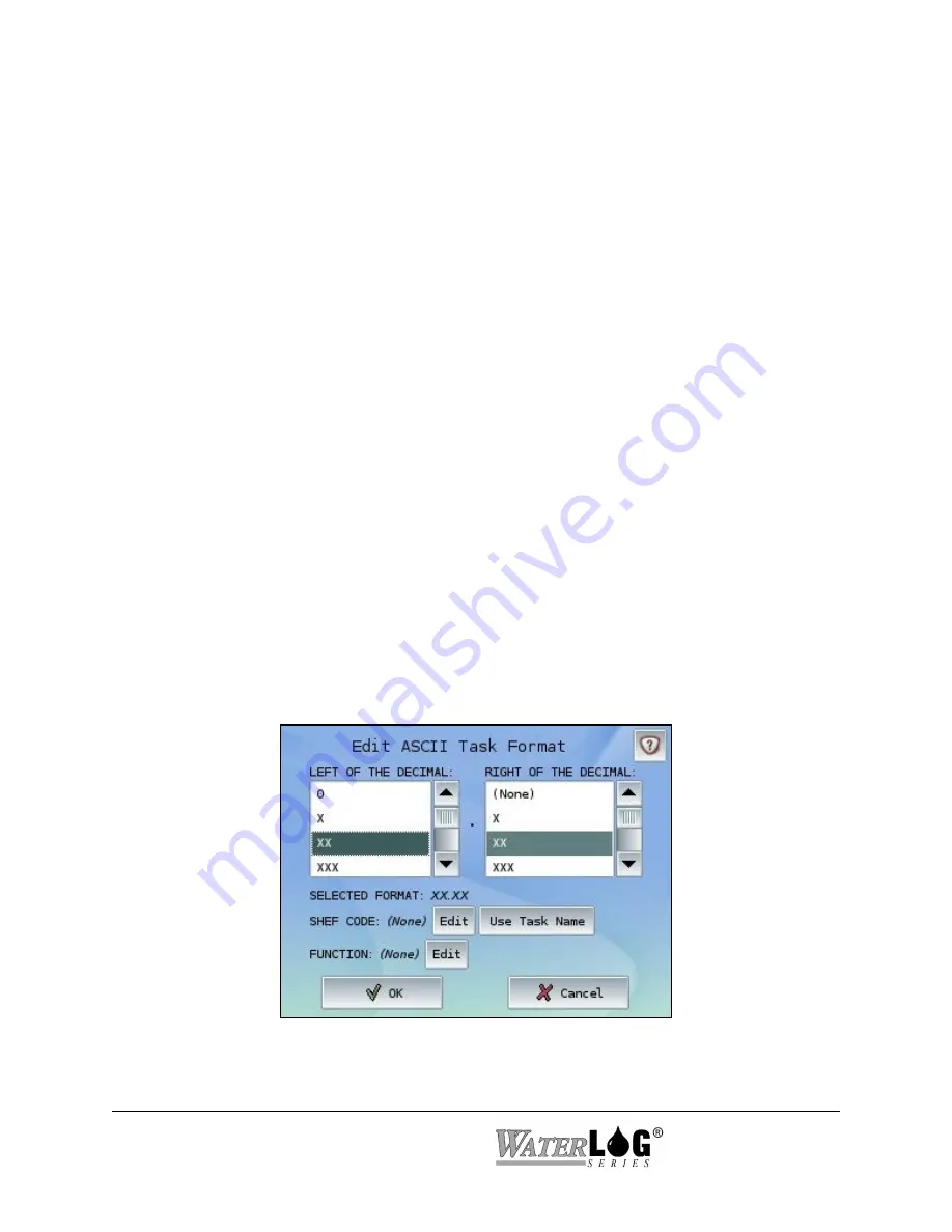
Depending on the Data Format (SHEF or Binary), one of the following Edit Task Format screens
will appear when the Edit Task button is pressed:
The Edit ASCII Task Format screen allows a desired format, SHEF Code and Function to be
chosen for the selected Task. If the entered SHEF code does not appear on the Data Setup
6-18 Outputs
System 5000
TM
Содержание WaterLog Series
Страница 1: ...Model System 5000TM Owner s Manual Revision 1 4 2...
Страница 2: ......
Страница 8: ......
Страница 24: ...2 10 Hardware Overview System 5000TM...
Страница 58: ...5 14 Inputs System 5000TM...
Страница 128: ...10 14 System Setup General Setup System 5000TM...
Страница 144: ...12 6 System Setup Inputs Outputs System 5000TM...
Страница 168: ...14 4 Maintenance and Troubleshooting System 5000TM...
Страница 170: ...A 2 System 5000 Specifications System 5000TM...
Страница 172: ...B 2 Pressure Sensor Option Module Specifications System 5000TM...
Страница 174: ...C 2 Analog Digital Option Module Specifications System 5000TM...


