


90
YORK INTERNATIONAL
begin counting downward to 0. The liquid line so-
lenoid of the compressor will open.
5.
After 4 seconds of run time,
the motor current of
the lead compressor must be >14% FLA and <115%
FLA. Oil pressure must be >5 PSID. If these condi-
tions are not met, the lead compressor will shut
down.
6.
After 30 seconds of run time,
the oil pressure of
the lead compressor must be a >20 PSID and the
suction pressure must be a >50% of cut-out. If
these conditions are not met, the lead compressor
will shut down.
7.
After 1 minute of run time,
the lead compressor
will load the 1st step, if cooling demand (tempera-
ture and rate control) requires.
8.
After 2 minutes of run time,
the lead compressor
will load the 2nd step, if cooling demand (tempera-
ture and rate control) requires.
9.
After 3 minutes of run time,
the lead compressor
will load the 3rd step, if temperature demand (tem-
perature and rate control) requires.
10.
After 4 minutes of operation,
the oil pressure of
the lead compressor must be >25 PSID and the
suction pressure must be > cut-out. If these condi-
tions are not met, the lead compressor will shut
down. If coolind demand requires (temperature and
rate control), the lag compressor will start unloaded
and its anti-recycle counter will begin counting back
to 0. The liquid line solenoid will open. The lead
compressor will unload 2 steps to its 1st step of 3
loading steps.
11.
After 4 minutes and 4 seconds of run time,
the
motor current of the lag compressor must be >14%
FLA and <115% FLA. Oil pressure must be >5 PSID.
If these conditions are not met, the lag compressor
will shut down.
12.
After 4 minutes and 30 seconds of run time,
the
oil pressure of the lag compressor must be >20
PSID and the suction pressure must be >50% cut-
out. If these conditions are not met, the lag com-
pressor will shut down.
13.
After 5 minutes of run time,
the lag compressor
will load to the 1st step of loading, if cooling de-
mand requires (temperature and rate control). The
lead compressor remains unchanged at the 1st step
of loading.
14.
After 6 minutes of run time,
the lead compressor
will load its 2nd step of loading, if cooling demand
requires (temperature and rate control). The lag com-
pressor remains unchanged at the 1st step of load-
ing.
15.
After 7 minutes of run time,
the lag compressor
will load to its 2nd step of loading, if cooling de-
mand requires.
16.
After 8 minutes of operation,
the oil pressure of
the lag compressor must be >25 PSID and the suc-
tion pressure must be > cut-out. If these conditions
are not met, the lag compressor will shut down (tem-
perature and rate control). The lead compressor will
load to its 3rd and final step of loading, if cooling
demand requires (temperature and rate control). The
lag compressor remains unchanged at the 2nd step
of loading.
17.
After 9 minutes of run time,
the lag compressor
will load to its 3rd and final step, if cooling demand
requires (temperature and rate control). The lead
compressor remains unchanged at the 3rd step of
loading.
OPERATING SEQUENCE UTILIZING LEAVING
WATER CONTROL
NOTE: The operating sequence described below relates
to operation after power has been applied on a
hot water start such as at start-up commission-
ing or a hot water start at the beginning of the
day. It also assumes that 10 steps of loading
are available and programmed. If less than 10
steps are available, no chiller response will take
place at some of the operating points described.
1. For the system compressors to run, all Manual
Reset Cut-outs must be reset, the Flow Switch must
be closed, any Remote Cycling Contacts must be
closed, the System Switches must be ON, the Daily
Schedule must be scheduling the chiller to run, and
temperature demand must be present.
2. As long as power is applied, the Crankcase Heat-
ers will be on and stay on as long as the compres-
sors are not running.
3. If power has just been applied to the system, the
microprocessor will start a 2 minute timer. This is
the same timer that prevents an instantaneous start
after a power failure. NOTE: Compressor Crankcase
Heaters should be on for a period of 24 hours prior
to commissioning. Failure to allow the heater suffi-
cient time to warm the oil may damage the com-
pressor due to liquid refrigerant in the oil.
4. At the end of the 2 minute timer, the microproces-
sor will check for cooling demand as well as check
Содержание YCRJ45E00
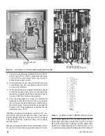
Страница 29: ...FORM 150 24 NM27 YORK INTERNATIONAL 29 CONTROL CIRCUIT With I O Expansion Board LD02106 ...
Страница 30: ...30 YORK INTERNATIONAL FIG 9 SYSTEM WIRING ...
Страница 31: ...FORM 150 24 NM27 YORK INTERNATIONAL 31 LD02678 ...
Страница 33: ...FORM 150 24 NM27 YORK INTERNATIONAL 33 LD02357 MOTOR TERMINAL BOX WIRING WITH MODEL 31AA MOTOR PROTECTOR ...
Страница 34: ...34 YORK INTERNATIONAL FIG 10 CONNECTION DIAGRAM LD02358 MICROPANEL CONNECTION DIAGRAM WITHOUT EXPANSION BOARD ...
Страница 35: ...FORM 150 24 NM27 YORK INTERNATIONAL 35 LD02679 ...
Страница 36: ...36 YORK INTERNATIONAL MICROPANEL CONNECTION DIAGRAM With I O Expansion Board LD02107 ...
Страница 37: ...FORM 150 24 NM27 YORK INTERNATIONAL 37 LD02108 ...


