FORM 150.24-NM27
YORK INTERNATIONAL
61
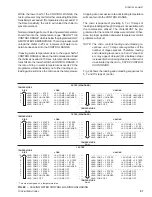
The next item which will require programming is the RATE
SENSITIVITY. The RATE SENSITIVITY is a means of
overriding the loading/unloading timers when water tem-
peratures are in the RATE CONTROL RANGE or the
CONTROL RANGE. This allows the micro to react to
abrupt downward changes in leaving or return water tem-
peratures. The ability to respond to rate of change varia-
tions in water temperatures gives the micro anticipa-
tion capabilities to reduce the possibility of overshoot
in leaving water temperature.
In demand limiting applications, to avoid cycling or to
avoid overshoot, RATE SENSITIVITY should be low. This
allows the micro to go into rate control to prevent loading
whenever water temperatures drop faster than the pro-
grammed RATE SENSITIVITY. Rate Control can go into
effect whenever water temperatures are in RATE CON-
TROL RANGE or the CONTROL RANGE. For these
applications, a 3°-5°F/min. RATE SENSITIVITY is rec-
ommended. This is also a must for small water loops.
However, if problems arise where the chiller does not
load and pull temperature down, select 5.0°F/min.
NOTE: Too small of a RATE SENSITIVITY value se-
lection may prevent loading due to varying flows
or if the water system allows a slug of cold water
to enter which falsely fools the micro into think-
ing the RATE SENSITIVITY has been exceeded,
preventing loading and allowing leaving water
temperature to rise above the desired tempera-
ture. In some cases, unloading or compressor
shutdown may result.
For normal comfort cooling, batch, or process applica-
tions, select a high RATE SENSITIVITY of 5.0°F/min.
Before RATE CONTROL can go into effect, the water
temperature would have to change at a very high rate to
exceed the RATE SENSITIVITY value programmed. This
will assure normal loading will occur. 5.0°F/min. also
works well in comfort cooling applications.
If unsure of
a RATE SENSITIVITY selection, use 5.0.F/min.
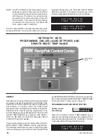
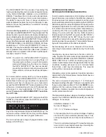
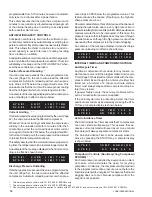
To program the RATE SENSITIVITY, first press the PRO-
GRAM key. Repetitively press the ENTER key until the
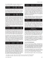
display below appears.
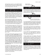
Key in the desired value and press the ENTER key. The
new value will be entered into memory and the display
will advance to the next user programmable limit.
The micro will accept a range of programmable values
between 0.5° - 5.0°F/min.
PROGRAMMING LEAVING WATER CONTROL
Chilled Liquid Temp/Range
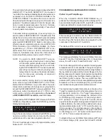
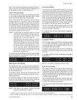
When the CHILLED LIQUID TEMP/RANGE key is
pressed, the following message will be displayed for 3
seconds indicating Dip Switch S1, Switch #4 on the Mi-
croprocessor Board is programmed properly:
If this message is incorrect, see the SELECTION OF
RETURN OR LEAVING CHILLED LIQUID CONTROL
Section (Page 50) for instructions to reprogram the Mi-
croprocessor Dip Switch S1, Switch #4.
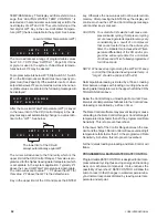
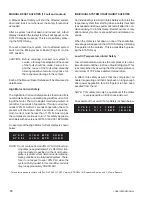
The display will then scroll to a second message & hold:
This message will display the Low-Limit Water Tempera-
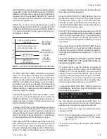
ture (LWT) and the Control Range (CR). In the sample
above, the LWT is 44.0°F and the CR is 44° - 46°F.
The Control Range (CR) is the variation in leaving water
temperature which is acceptable in the system applica-
tion. As long as leaving water temperature stays between
the low limit and midpoint of the Control Range (CR), the
Microprocessor will consider the temperature acceptable
and will not initiate any loading/unloading reaction un-
less Rate Control requires. The Low-Limit Water Tem-
perature (LWT) is the minimum acceptable leaving water
temperature in the Control Range (CR), not the actual
user desired leaving water temperature setpoint.
The desired leaving water temperature is known as the
Target temperature which is the temperature the micro
will attempt to control too. The Target temperature is
not programmable, but it is always the midpoint of the
Control Range (CR). Example: A control range of 44°-
46°F will have a Target Temp of 45°F, which should
equal the desired system leaving water temperature. As
mentioned before, the micro will be satisfied with a leav-
ing temperature between 44° - 45°F unless the rate con-
trol is exceeded. The microprocessors rate control is
designed to be less responsive in the upper half of the
Control Range (i.e. 45° - 46°F) than in the lower half (i.e.
44° - 45°F). This is to prevent overshoot.
To program the Low-Limit Water Temperature (LWT) and
the Control Range (CR), press the CHILLED LIQUID
R A T E
S E N S I T I V I T Y
=
5 . 0
F / M I N
L W T =
4 4 . 0
F
C R =
4 4 . 0
T O
4 6 . 0
F
L E A V I N G
W A T E R
T E M P
C O N T R O L
Содержание YCRJ45E00
Страница 29: ...FORM 150 24 NM27 YORK INTERNATIONAL 29 CONTROL CIRCUIT With I O Expansion Board LD02106 ...
Страница 30: ...30 YORK INTERNATIONAL FIG 9 SYSTEM WIRING ...
Страница 31: ...FORM 150 24 NM27 YORK INTERNATIONAL 31 LD02678 ...
Страница 33: ...FORM 150 24 NM27 YORK INTERNATIONAL 33 LD02357 MOTOR TERMINAL BOX WIRING WITH MODEL 31AA MOTOR PROTECTOR ...
Страница 34: ...34 YORK INTERNATIONAL FIG 10 CONNECTION DIAGRAM LD02358 MICROPANEL CONNECTION DIAGRAM WITHOUT EXPANSION BOARD ...
Страница 35: ...FORM 150 24 NM27 YORK INTERNATIONAL 35 LD02679 ...
Страница 36: ...36 YORK INTERNATIONAL MICROPANEL CONNECTION DIAGRAM With I O Expansion Board LD02107 ...
Страница 37: ...FORM 150 24 NM27 YORK INTERNATIONAL 37 LD02108 ...

