22
YORK INTERNATIONAL
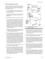
1/16" or 1/8' thick neoprene) should be used be-
tween the pipe and a pipe support. This will prevent
metal-to-metal contact and possible chatter between
the pipe and its supports. Supports must be installed
in such a way as to prevent transmission of exces-
sive vibration to building structures.
14. Where pipe passes through a wall, the space be-
tween the pipe and the wall must be filled with a
resilient material such as cork, fiberglass, etc. The
pipe must not touch the wall.
15. A relatively large mass of pipe (such as a common
discharge or suction header or trap on a parallel sys-
tem or a discharge oil separator) must be held rig-
idly in three coordinate directions so it is immov-
able. Vibration must be effectively isolated from the
building structure with appropriate resilient materi-
als.
16. A discharge muffler (if used) should be in a horizon-
tal line, after the first support, as close to the unit as
possible and should be placed between the com-
pressor and discharge oil separator (which is gen-
erally used with refrigeration systems only). The oil
return line from a separator must not drop straight
down into the compressor crankcase but must have
a 2-foot minimum horizontal run before it enters the
compressor to allow flexibility.
17. Under no circumstances should a suction or dis-
charge connection to a compressor run directly in a
straight line to a rigid connection or support in a
horizontal plane perpendicular to the crankshaft axis.
Torsional movement, vibration effects and thermal
growth could prove too severe.
The preceding comments will assist the piping de-
signer and installer but are not necessarily all inclu-
sive of what may be needed to avoid problems: The
contractor has the responsibility for correcting field
problems with piping and the potential liability for
injury to personnel. He, therefore, should consult the
following two ANSI and ASHRAE documents for his
design and installation practices:
a. ASHRAE Standard Safety Code for Mechanical
Refrigeration ANSI/ASHRAE 15- 1978. The
American Society of Heating, Refrigerating, and
Air Conditioning Engineers, Inc., 345 East 47th
Street, New York, NY 10017.
b. American National Standard Code for Pressure
Piping, ANSI B31.5 - 1974. The American Soci-
ety of Mechanical Engineers, United Engineer-
ing Center, 345 East 47th Street, New York, NY
10017.
Since YCR chillers are shipped containing Refriger-
ant-22 as a holding charge, the compressor discharge
valve and the liquid stop valve should be kept closed
until the remote condenser and all refrigerant piping are
installed, tested and properly evacuated for removal of
moisture as explained under FIELD REFRIGERANT PIP-
ING opposite.
HIGH SIDE EQUIPMENT
The proper selection of remote condensers, receivers
and relief valves must be made for use in conjunction
with condenserless YCR model chillers. To comply with
the ANSI B9.1 Safety Code, the following must be ad-
hered to.
HPCO setting (PSIG) =
90% of pressure relief device
setting on the high side
The mechanical HP cut-out in the YCW chiller is set for
270 PSIG, corresponding to a maximum design pres-
sure of 300 PSIG. To permit operation and permit startup
at high ambients and chilled water temperatures, up to
150°F saturated compressor discharge, the YCR model
chiller has its HP cut-out set at 360 PSIG +10 PSIG.
Per ANSI B9.1, the maximum setting of the HP cut-out
is 90% of the relief device setting or shell design working
pressure (DWP), whichever is smaller. Whereas 300 PSIG
DWP receivers and relief devices are adequate for mod-
els operating up to 120°F condensing temperature, YCR
models which operate at higher condensing pressures
must have minimum DWP and relief settings of 450 psi
(405
÷
.9)
FIELD REFRIGERANT PIPING
YCR (REMOTE CONDENSER TYPE) UNITS
INTERNAL DRYNESS AND CLEANLINESS It is es-
sential that unit compressors be installed and operated
in a refrigerant piping system which is thoroughly dry
and clean. Compressors are internally clean, free of
moisture and ready for satisfactory operation when they
leave the factory. However, if they are installed or oper-
ated in a refrigerant system which is contaminated with
moisture and/or foreign material, they may be damaged
seriously. The dryness and cleanliness of the refrigerant
system in which the compressor will operate is beyond
the control of the manufacturer since the remote con-
denser and the associated refrigerant discharge and liq-
uid piping is installed in the field.
It is the responsibility of field personnel to see that refrig-
erant systems are installed dry and clean and that they
are maintained this way during operation.
EFFECTS OF MOISTURE AND AIR If the system con-
tains moisture, corrosion of internal parts may take place.
Содержание YCRJ45E00
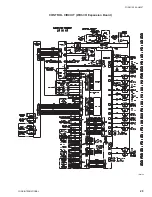
Страница 29: ...FORM 150 24 NM27 YORK INTERNATIONAL 29 CONTROL CIRCUIT With I O Expansion Board LD02106 ...
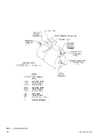
Страница 30: ...30 YORK INTERNATIONAL FIG 9 SYSTEM WIRING ...
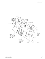
Страница 31: ...FORM 150 24 NM27 YORK INTERNATIONAL 31 LD02678 ...
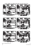
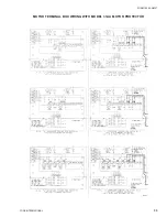
Страница 33: ...FORM 150 24 NM27 YORK INTERNATIONAL 33 LD02357 MOTOR TERMINAL BOX WIRING WITH MODEL 31AA MOTOR PROTECTOR ...
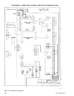
Страница 34: ...34 YORK INTERNATIONAL FIG 10 CONNECTION DIAGRAM LD02358 MICROPANEL CONNECTION DIAGRAM WITHOUT EXPANSION BOARD ...
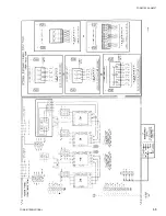
Страница 35: ...FORM 150 24 NM27 YORK INTERNATIONAL 35 LD02679 ...
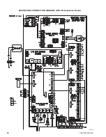
Страница 36: ...36 YORK INTERNATIONAL MICROPANEL CONNECTION DIAGRAM With I O Expansion Board LD02107 ...
Страница 37: ...FORM 150 24 NM27 YORK INTERNATIONAL 37 LD02108 ...

