


FORM 150.24-NM27
YORK INTERNATIONAL
13
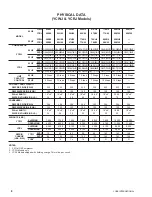
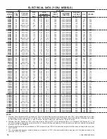
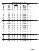
SYSTEM #2
MIN.
1
DUAL
NON-
INCOMING
MAX SIZE
CIR. ELEM FUSE
FUSED
4
WIRE SIZE
6
CKT BKR
RLA PW/LRA
AMP. MIN.
2
MAX.
3
DISC.SW
HACR TYPE
5
251
300
450
400
(2) #4-250MCM
450
200
731
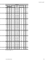
226
300
400
400
(2) #4-250MCM
400
180
636
132
175
225
200
(2) #4-250MCM
225
105
385
113
150
200
200
(2) #4-250MCM
200
90
318
126
150
225
200
(2) #4-250MCM
225
100
410
88
110
150
100
(2) #4-250MCM
150
70
254
138
175
225
200
(2) #4-250MCM
225
110
412
251
300
450
400
(2) #4-250MCM
450
200
731
226
300
400
400
(2) #4-250MCM
400
180
636
132
175
225
200
(2) #4-250MCM
225
105
385
113
150
200
200
(2) #4-250MCM
200
90
318
126
150
225
200
(2) #4-250MCM
225
100
410
88
110
150
100
(2) #4-250MCM
150
70
254
138
175
225
200
(2) #4-250MCM
225
110
412
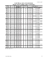
291
350
500
400
(2) #4-250MCM
500
232
865
258
350
450
400
(2) #4-250MCM
450
206
752
151
200
250
200
(2) #4-250MCM
250
120
412
129
175
225
200
(2) #4-250MCM
225
103
376
149
200
250
200
(2) #4-250MCM
250
119
482
99
125
175
100
(2) #4-250MCM
175
79
300
164
200
250
200
(2) #4-250MCM
250
131
572
291
350
500
400
(2) #4-250MCM
500
232
865
258
350
450
400
(2) #4-250MCM
450
206
752
151
200
250
200
(2) #4-250MCM
250
120
412
129
175
225
200
(2) #4-250MCM
225
103
376
149
200
250
200
(2) #4-250MCM
250
119
482
99
125
175
100
(2) #4-250MCM
175
79
300
164
200
250
200
(2) #4-250MCM
250
131
572
376
450
600
400
(2) 1/0-500MCM
600
300
1101
331
400
500
400
(2) #4-250MCM
500
264
976
198
250
350
200
(2) #4-250MCM
350
158
591
166
200
250
200
(2) #4-250MCM
250
132
488
186
225
300
200
(2) #4-250MCM
300
148
585
132
175
225
200
(2) #4-250MCM
225
105
390
203
250
350
200
(2) #4-250MCM
350
162
668
376
450
600
400
(2) 1/0-500MCM
600
300
1101
331
400
500
400
(2) #4-250MCM
500
264
976
198
250
350
200
(2) #4-250MCM
350
158
591
166
200
250
200
(2) #4-250MCM
250
132
488
186
225
300
200
(2) #4-250MCM
300
148
585
132
175
225
200
(2) #4-250MCM
225
105
390
203
250
350
200
(2) #4-250MCM
350
162
668
469
600
800
600
(2) 1/0-500MCM
800
375
1101
408
500
700
400
(2) #4-250MCM
700
326
976
241
300
400
400
(2) #4-250MCM
400
192
591
204
250
350
200
(2) #4-250MCM
350
163
488
236
300
400
400
(2) #4-250MCM
400
188
760
159
200
250
200
(2) #4-250MCM
250
127
390
258
350
450
400
(2) #4-250MCM
450
206
917
296
400
500
400
(2) #4-250MCM
500
236
997
244
300
400
400
(2) #4-250MCM
400
195
830
196
250
350
200
(2) #4-250MCM
350
156
664
LEGEND
VOLT
= Voltage
MCA
= Minimum Circuit Ampacity
DIS
= Disconnect
ACL
= Across-the-Line
PW
= Part Wind
N/A
= Not Available
RLA
= Running Load Amps
FLA
= Full Load Amps
ACL/LRA = Across-the-Line Inrush Amps
PW/LRA = Part Wind Inrush Amps
CKT BRK = Circuit Breaker
HACR
= Heating, Air Conditioning, and
Refrigeration
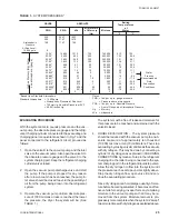
5. Maximum HACR is based on 225% maximum plus 100% of the rated load amps for all loads included in the circuit, per circuit, per U.L. 1995
Fig 36.2.
6. The INCOMING WIRE RANGE is the minimum and maximum wire size that can be accommodated by the unit wiring lugs. The (1), (2), (3),
or (4) preceding the wire range indicates the number of termination points available per phase of the wire range specified. The (1-3)
preceding the wire range indicates that a single double-barreled lug is available per phase that can accept up to three wires of the wire
range specified. (1) #1-600MCM OR (2) #1-250MCM indicates that a single lug is supplied and it will accept a single wire up to 600MCM or
2 wires up to 250MCM. Actual wire size and number of wires per phase must be determined based on ampacity and job requirements using
N.E.C. wire sizing information. The above recommendations are based on the National Electrical Cold and using copper connectors only.
Field wiring must also comply with local codes.
7. A ground lug is provided for each compressor system to accommodate field grounding conductor per N.E.C. Article 250-54. A control circuit
grounding lug is also supplied. Incoming ground wire range is #6 - #2/0.
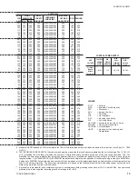
CONTROL POWER SUPPLY
CONTROL
MIN.
MAX.
NON-FUSE
UNIT
POWER
CIRCUIT
DUAL-
DISC.
VOLTAGE
SUPPLY
AMPACITY
ELEMENT
SWITCH
FUSE SIZE
SIZE
Standard
Models
115-1-60
20A
20A, 250V
30A, 240V
Without
Transformers
Содержание YCRJ45E00
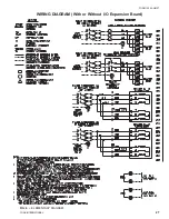
Страница 29: ...FORM 150 24 NM27 YORK INTERNATIONAL 29 CONTROL CIRCUIT With I O Expansion Board LD02106 ...
Страница 30: ...30 YORK INTERNATIONAL FIG 9 SYSTEM WIRING ...
Страница 31: ...FORM 150 24 NM27 YORK INTERNATIONAL 31 LD02678 ...
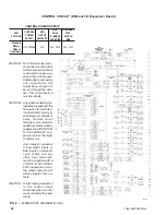
Страница 33: ...FORM 150 24 NM27 YORK INTERNATIONAL 33 LD02357 MOTOR TERMINAL BOX WIRING WITH MODEL 31AA MOTOR PROTECTOR ...
Страница 34: ...34 YORK INTERNATIONAL FIG 10 CONNECTION DIAGRAM LD02358 MICROPANEL CONNECTION DIAGRAM WITHOUT EXPANSION BOARD ...
Страница 35: ...FORM 150 24 NM27 YORK INTERNATIONAL 35 LD02679 ...
Страница 36: ...36 YORK INTERNATIONAL MICROPANEL CONNECTION DIAGRAM With I O Expansion Board LD02107 ...
Страница 37: ...FORM 150 24 NM27 YORK INTERNATIONAL 37 LD02108 ...


