20
YORK INTERNATIONAL
A strainer, preferably 40 mesh,
MUST
be installed in the
cooler and condenser inlet lines, just ahead of the cooler
and condenser.
A small valve or valves should be installed at the highest
point or points in the chilled liquid piping to allow any
trapped air to be purged. Vent and drain connections
should be extended beyond the insulation to make them
accessible. Chiller piping as well as the circulating pump
may be insulated as required to prevent condensation
from forming.
CHILLED LIQUID PIPING
The piping to and from the cooler must be designed to
suit the individual installation. It is important that the
following considerations be observed:
1. The chilled liquid piping system should be laid out
so that the circulating pump discharge is into the
cooler. The suction for this pump should be taken
from the piping system return line and not the cooler.
2. It is recommended that all chilled liquid piping be
thoroughly flushed to free it from foreign material be-
fore the system is placed into operation. Use care
not to flush any foreign material into or through the
cooler.
3. As an aid to servicing, thermometers and pressure
gauges should be installed in the inlet and outlet
water lines. One connection point (plugged) is pro-
vided in each cooler nozzle. Thermometers and
gauges are not furnished with the unit and are to be
furnished by other suppliers.
4. A chilled water flow switch, (either by YORK or oth-
ers)
MUST
be installed in the leaving water piping of
the cooler. There should be a straight horizontal run
of at least 5 diameters on each side of the switch.
Adjust the flow switch paddle to the size of pipe in
which it is to be installed. (See manufacturers in-
structions furnished with switch). The switch is to
be wired to terminals in the control panel as shown
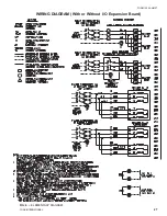
in the WlRING DIAGRAM.
CONDENSER WATER PIPING
Water cooled condensers may be piping for well water
or for use in conjunction with a water cooling tower.
1. WELL WATER If well water with a temperature be-
low 55°F is used to cool the condenser, some means
must be provided to maintain adequate condenser
pressure for proper operation of the expansion valve.
One way to control condenser pressure is to use an
automatic water regulating valve to maintain a mini-
mum leaving water temperature of 65°F .
The regulator should be installed in the entering water
line; however, the outlet piping leaving the condenser
should contain a vertical rise approximately 3" higher
than the top of the condenser before an elbow is in-
stalled to continue the piping to an open drain. The
reason for the vertical riser is to create a trap which
will prevent water from draining out of the condenser
at each shut down. This aids in preventing unneces-
sary and premature fouling of the condenser due to
drying of the tubes (with subsequent rapid build up of
foreign material) during shutdown periods.
It should be determined that the maximum water pres-
sure at the condenser does not exceed the maximum
design working pressure of the condenser (150 PSIG).
In order to insure quiet and satisfactory operation of
the water regulating valve, the manufacturer may limit
the working pressure to which the valve can be sub-
jected.
Where excessive water pressures are encountered, a
pressure reducing valve should be installed ahead of
the water regulating valve to permit reduction of the
condenser water pressure in accordance with the re-
quirements of the condenser and/or water regulating
valve.
2. WATER COOLING TOWER PIPING When install-
ing these chillers with a cooling tower, some means
of controlling head pressure must be provided if op-
eration with entering condenser water temperature
below 55°F is required. Water flow through the cool-
ing tower should be constant, while at the same time,
it must be possible to vary the water flow through the
condenser to keep the condensing pressure and tem-
perature constant regardless of load and outside tem-
perature and wet bulb conditions to assure proper
operation of the thermal expansion valve or valves.
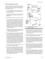
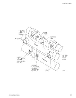
This may be accomplished by installing a 3-way wa-
ter regulating valve as shown in Fig. 6. The valve should
be set to maintain 65°F minimum leaving condenser
water temperature.
The use of a three way water regulating valve with
bypass is highly recommended since it maintains con-
stant condensing pressure regardless of outside tem-
perature conditions and insures proper operation of
the cooler expansion valve.
It is important to follow the instructions of the water
regulating valve manufacturer in regard to installation
recommendations and valve adjustment procedures.
Thermometer wells should be located at the condenser
inlet and outlet to aid in performance and service work.
Содержание YCRJ45E00
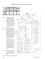
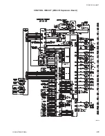
Страница 29: ...FORM 150 24 NM27 YORK INTERNATIONAL 29 CONTROL CIRCUIT With I O Expansion Board LD02106 ...
Страница 30: ...30 YORK INTERNATIONAL FIG 9 SYSTEM WIRING ...
Страница 31: ...FORM 150 24 NM27 YORK INTERNATIONAL 31 LD02678 ...
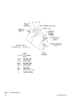
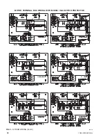
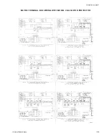
Страница 33: ...FORM 150 24 NM27 YORK INTERNATIONAL 33 LD02357 MOTOR TERMINAL BOX WIRING WITH MODEL 31AA MOTOR PROTECTOR ...
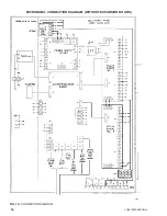
Страница 34: ...34 YORK INTERNATIONAL FIG 10 CONNECTION DIAGRAM LD02358 MICROPANEL CONNECTION DIAGRAM WITHOUT EXPANSION BOARD ...
Страница 35: ...FORM 150 24 NM27 YORK INTERNATIONAL 35 LD02679 ...
Страница 36: ...36 YORK INTERNATIONAL MICROPANEL CONNECTION DIAGRAM With I O Expansion Board LD02107 ...
Страница 37: ...FORM 150 24 NM27 YORK INTERNATIONAL 37 LD02108 ...

