FORM 150.24-NM27
YORK INTERNATIONAL
23
Moisture build-up in a system is frequently gradual. A
corrosive condition can exist before the moisture con-
tent has built up to the point where freeze-up of the ex-
pansion device may be possible. Moisture in the system
can combine with Refrigerant-22 to form acid. The acid
corrodes the internal parts of the system, particularly
compressor parts. This can be a factor in causing motor
burnouts. Frequently, these parts become corroded to
the point where they are unfit for further use. Also, sludge
is formed, which causes driers and screens to become
plugged. The extent of corrosion when present depends
on the amount of acid, the operating temperature and
the length of time the system has been operating in an
acid-forming condition.
Air and moisture are closely associated: when air exists
in the system, moisture is usually present.
Air raises the operating discharge pressure, which re-
sults in un-economical operation and higher compressor
operating temperatures. The adverse effects of air and
moisture are more serious at high temperatures, the lat-
ter being the direct result of high condensing pressures,
which in turn, may be caused by the presence of air in
the system.
FOREIGN MATERIAL Dirt, rust, scale and any foreign
material may damage compressor parts and must be
prevented from reaching these parts. Refrigerant-22 acts
as a solvent and may loosen foreign material from the
interior surfaces of the piping. Care must be taken to
prevent this material from being flushed back through
the suction connection and into the compressor. All pip-
ing should be thoroughly cleaned at the time of installa-
tion to eliminate foreign material at its source.
INSTALLATION It is important that all precautions be
taken to avoid the entrance of moisture and foreign ma-
terial DURING the installation procedure. Pipes, coil
connections, or any refrigerant-containing portions of the
system should not be allowed to remain open even for
an overnight period. All such openings should be plugged
or temporarily sealed. The compressor discharge stop
valves and the refrigerant liquid stop valve should remain
closed during fabrication of the condenser piping sys-
tem. They should be opened just before the system is
evacuated, tested and charged with refrigerant. Filter drier
cores should not be exposed to the air for more than 10
minutes.
YCR models must include discharge line mufflers. The
mufflers should be mounted in the discharge line as close
to the unit as possible. They can be mounted vertically
or horizontally but should never be installed in a riser.
One side of the muffler is stamped TOP for horizontal
mounting. The mufflers should always be pitched toward
the condenser.
YCR models with optional Hot Gas Bypass (Loadmin-
der) require field piping to be completed to the discharge
side of the system piping.
LOW AMBIENT APPLICATION
Starting
When chillers are applied with air-cooled or evaporative
condensers, provisions are necessary to allow starting
at lower than design outside ambient since the evapo-
rator is usually pumped down and there may not be suf-
ficient pressure at the outside ambient to supply liquid
to the evaporator.
Operation
Full capacity may be required at lower than design am-
bient. Then it is necessary to maintain system head pres-
sure for proper expansion valve pressure differential for
satisfactory evaporator feeding. This may be accom-
plished with an air cooled condenser or evaporative con-
denser by any appropriate means such as: A damper
control system or fan cycling on the air-cooled or evapo-
rative condenser or by backing up liquid in the condenser.
Water cooled condensers are usually controlled by a
pressure regulating valve throttling the cooling water or
by a cooling tower bypass valve. If this is overlooked, a
problem is almost a certainty in multiple chiller installa-
tions and likely on single unit applications.
TESTING
YCW models are shipped fully charged with refriger-
ant. YCR models are shipped with a refrigerant holding
charge.
For field installed YCR models, it is recommended that
the holding charge be released and the entire system
(chiller, condenser and associated piping) be evacuated,
tested and dehydrated before charging refrigerant. In this
case, the connection for evacuating and charging may
be attached to the charging port of the refrigerant liquid
stop valve as explained under CHARGING CON-
NECTIONS. Also, it will be necessary to hold the liquid
line solenoid valve in the open position by energizing it
from an outside source of current.
Before the evacuation process can proceed, the refrig-
erant-containing portions of the system must be free of
leakage. It is recommended that a pressure of 150 PSIG
(Refrigerant-22 and dry nitrogen) be applied to the sys-
tem for testing. This may be accomplished by connecting
a cylinder of Refrigerant-22 to the charging port of the
condenser liquid stop valve and bleeding in enough re-
frigerant gas to bring the system pressure to approxi-
mately 25 PSIG. At this point a rapid inspection for ma-
jor leaks should be made. If any are found, the pressure
Содержание YCRJ45E00
Страница 29: ...FORM 150 24 NM27 YORK INTERNATIONAL 29 CONTROL CIRCUIT With I O Expansion Board LD02106 ...
Страница 30: ...30 YORK INTERNATIONAL FIG 9 SYSTEM WIRING ...
Страница 31: ...FORM 150 24 NM27 YORK INTERNATIONAL 31 LD02678 ...
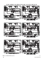
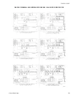
Страница 33: ...FORM 150 24 NM27 YORK INTERNATIONAL 33 LD02357 MOTOR TERMINAL BOX WIRING WITH MODEL 31AA MOTOR PROTECTOR ...
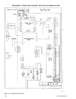
Страница 34: ...34 YORK INTERNATIONAL FIG 10 CONNECTION DIAGRAM LD02358 MICROPANEL CONNECTION DIAGRAM WITHOUT EXPANSION BOARD ...
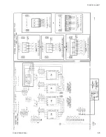
Страница 35: ...FORM 150 24 NM27 YORK INTERNATIONAL 35 LD02679 ...
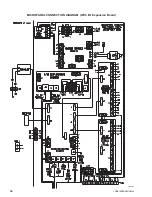
Страница 36: ...36 YORK INTERNATIONAL MICROPANEL CONNECTION DIAGRAM With I O Expansion Board LD02107 ...
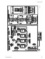
Страница 37: ...FORM 150 24 NM27 YORK INTERNATIONAL 37 LD02108 ...

