


FORM 150.40-NM20
53
YORK INTERNATIONAL
1. Panel Switches
A. Set the Return Chilled Water Temp. to the desired
temperature. (This will be leaving water temp. setpoint
if this option is utilized.)
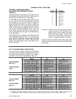
B. Assure the Micro Logic Board jumpers/switches
are configured for the unit design and the system’s
requirement. See pages 58 & 59.
2. Place the System Switches to the ON position. See
the OPERATING SEQUENCE for unit operation.
The compressor will start and a flow of liquid should
be noted in the liquid indicator. After several minutes
of operation, the bubbles should disappear and there
will be a solid column of liquid when the unit is oper-
ating normally. On start-up, foaming of the oil may
be evident in the compressor oil sightglass. After the
water temperature has been pulled down to operat-
ing conditions, the oil should be clear. Normal opera-
tion of the unit is evidenced by a hot discharge line,
clear oil in the compressor crankcase, solid liquid
refrigerant in the liquid indicator and usually no more
than 2 PSIG variation in suction pressure for any
given set of operating conditions. Check direction of
fan rotation. Air flow must be “up”.
Allow the compressor to run for a short time, being
ready to stop it immediately if any unusual noise or
other adverse condition should develop. When start-
ing the compressor, always make sure the oil pump
is functioning properly. Compressor oil pressure must
be as described under “Oil Pressure Cutout” (See
Control Description).
Check the system operating parameters. Do this by
selecting various readouts such as pressure and tem-
perature. Compare these to test gauge readings.
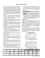
CHECKING SUPERHEAT AND SUBCOOLING
The subcooling should always be checked when charg-
ing the system with refrigerant and/or before setting the
superheat.
When the refrigerant charge is correct, there will be no
bubbles in the liquid sightglass with the system operat-
ing under full load conditions, and there will be 10° to
15°F subcooled liquid leaving the condenser.
An overcharged system should be guarded against.
Evidences of overcharge are as follows:
a. If a system is overcharged, the discharge pressure
will be higher than normal. (Normal discharge pres-
sure can be found in refrigerant temperature/pres-
sure chart; use ambient tempe30°F for nor-
mal condensing temperatures.
b. The temperature of the liquid refrigerant out of the
condenser should not be more than 15°F less than
the condensing temperature. (The temperature cor-
responding to the condensing pressure from refrig-
erant temperature/ pressure chart.)
(YCHA120, 150, 175 & 200)
The subcooling temperature should be taken by record-
ing the temperature of the liquid line at the outlet of the
con” denser and recording the liquid pressure at the
liquid service valve and converting it to a temperature
from temperature/pressure chart.
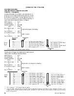
Example:
Liquid Line Pressure 260 PSIG converted to
120°F
Minus Liquid Line Temperature Subcooling
105°F
= to
15°F
Add refrigerant to the system to increase subcooling or
remove to lower.
After the subcooling is set at 10-15°F the superheat
should be checked.
The superheat should be checked only after steady
operation of the chiller has been established, the leav-
ing chilled liquid has been pulled down to the required
temperature, and the unit is running fully loaded. Cor-
rect superheat setting is 8° - 12°F.
The superheat is the difference between the actual
temperature of the returned refrigerant gas entering the
compressor and the temperature corresponding to the
suction pressure as shown in a standard pressure/tem-
perature chart.
Example:
Suction Temperature
44°F
Minus Suction Pressure 60 PSIG
34°F
Converted to Superheat
10°F
The suction temperature should be taken 6" before the
compressor service valve, and the suction pressure is
taken at the compressor suction service valve.
Normally, the thermal expansion valve need not be ad-
justed in the field. If, however, an adjustment is to be
made, the expansion valve adjusting screw should be
turned not more than one turn at a time, allowing suffi-
cient time (approximately 20 minutes) between adjust-
ments for the system and the thermal expansion valve
to respond and return to settled operation. Make sure
that expansion valve is not cycling by watching pres-
sures and temperatures during the waiting period. If the
unit has been functioning satisfactorily during the initial
operating period, it is ready for continuous operation.
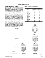
OPERATING SEQUENCE
(ALSO SEE COMPRESSOR CAPACITY CONTROL)
1. For the system compressors to run, all Manual Re-
set Cutouts must be reset, the Flow Switch must be
closed, and any remote cycling contacts must be
closed.
2. As long as power is applied, the Crankcase Heaters
will be on and stay on as long as the compressors
are not running.
3. When the System Power Switch is applied, the unit
will start a 2 minute start-up timer.
Содержание YCAQ10
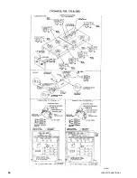
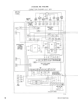
Страница 20: ...YORK INTERNATIONAL 20 LD01779 YCHA100 FIG 9 WIRING DIAGRAM YCHA100...
Страница 21: ...FORM 150 40 NM20 21 YORK INTERNATIONAL YCHA100 LD01779 D...
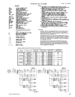
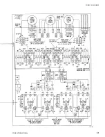
Страница 22: ...YORK INTERNATIONAL 22 LD01780 L YCHA100 FIG 9 Continued...
Страница 23: ...FORM 150 40 NM20 23 YORK INTERNATIONAL LD01780 R YCHA100...
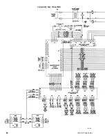
Страница 24: ...YORK INTERNATIONAL 24 YCHA100 LD01781 FIG 9 Continued...
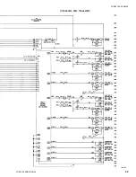
Страница 25: ...FORM 150 40 NM20 25 YORK INTERNATIONAL LD01782 YCHA100...
Страница 46: ...YORK INTERNATIONAL 46 LD01787...
Страница 47: ...FORM 150 40 NM20 47 YORK INTERNATIONAL LD01788...
Страница 48: ...YORK INTERNATIONAL 48 LD01789...
Страница 49: ...FORM 150 40 NM20 49 YORK INTERNATIONAL LD01790...
Страница 50: ...YORK INTERNATIONAL 50 LD01791...
Страница 51: ...FORM 150 40 NM20 51 YORK INTERNATIONAL LD01792...
Страница 77: ......
Страница 78: ......
Страница 79: ......
Страница 80: ......
Страница 81: ......
Страница 82: ......
Страница 83: ......
Страница 84: ......
Страница 85: ......
Страница 86: ......
Страница 87: ......
Страница 88: ......
Страница 89: ......
Страница 90: ......
Страница 91: ......
Страница 92: ......
Страница 93: ......
Страница 94: ......
Страница 95: ......
Страница 96: ......
Страница 97: ......
Страница 98: ......
Страница 99: ......