


FORM 150.40-NM20
41
YORK INTERNATIONAL
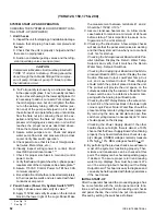
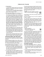
FAULT CODE DIAGNOSIS
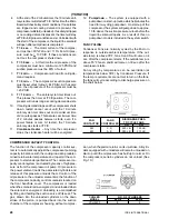
Any time an “F” code is displayed, one of the compres-
sors will be shut down. The operator should then place
the “SELECT DATA DISPLAY” rotary switches to “18”. This
will cause a number from 0 to 11 to be displayed. This
number can be referenced to the “Fault Codes” which tell
tile operator which system failed and what the cause was.
At the time of a Fault, the microprocessor stores
operating data on both systems at the instant of
shutdown. Any display selected by the operator will
show stored data. This data will remain in storage until
the SYSTEM Switch for the faulted compressor is placed
in the OFF position. This clears the microprocessor’s
memory of stored data, and any display at this time will
be of current system conditions. It also allows the faulted
compressor to start.
Before placing the SYSTEM Switch to the OFF posi-
tion, the operator may (via the “SELECT DATA DIS-
PLAY” rotary switches) select the parameter which
caused the fault, and any other related system func-
tion, and view their magnitudes at the time of the fail-
ure. This can provide valuable trouble-shooting infor-
mation. Detailed explanations of all system safeties are
included in the “START-UP SECTION”.
Both Systems Down on a Fault: The “F” code will be
displayed and the associated stored data applies to both
system conditions at the time of the1st Fault. A “.” will
appear next to the “F” or “F.”. This is the indication that
both systems are down on a Fault.
After clearing the 1st Fault, an “F” code will still be
displayed, but without the “.”. The stored data will still
be that which was stored at the time of the 1st Fault.
This will probably not provide any levels which were out
of the allowed operating range for the second Fault,
unless the Fault related to low leaving water tempera-
ture which affects both systems. This type of Fault oc-
curs simultaneously on both systems and will require
both System Switches to simultaneousIy be placed in
the off position to clear. This can only be accomplished
after temperature rises above the cut-out point.
After clearing the Fault(s), placing the SYSTEM
Switch(s) to the ON position will cause a normal start
sequence to begin unless the problem causing the origi-
nal trouble is still causing safety thresholds to be ex-
ceeded. If this occurs, an “F” code will then reappear.
Note: The trouble may not immediately show up and
the system may run for awhile.
CAUTION: Anytime a system shuts down on a Fault,
steps should be taken to find and eliminate
the cause of the problem before attempting
to restart the system.
The operator should also be aware that be-
fore the unit will display an “F” code, the prob-
lem system has already shut down twice on a
fault and restarted within the last 90 minutes.
This insures that the system will not shut down
and lock out on a nuisance trip or if the sys-
tem is operating under marginal conditions.
The system will shut down instantly when a Manual
Reset Fault is sensed, but it will allow automatic restart
until it sees a total of any 3 Faults in a 90-minute pe-
riod. A 90-minute counter is started as soon as the 1st
Fault occurs. If 2 more faults do not occur in the next 90
minutes, the counter is reset to “0”.
After a fault, restart cannot be expected until the anti-
recycle timers time out. No display (“F” Code) will be
indicated during the first two faults except for a letter code
telling the operator the anti-recycle timer is in effect.
After 3 faults, an “F” code will be displayed and the sys-
tem will not restart. The fault can be cleared and the
compressor restarted by placing the System Off/On
Switch to the OFF position. However another fault will
shut down the system and an “F” code will be displayed.
The system will continue to shut down on every Fault
until the problem system runs without faulting for 90
minutes or until power is cycled. Recycling power will
reset the counter.
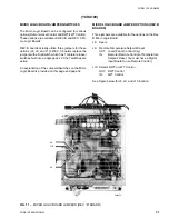
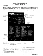
SYSTEM COMPONENTS
Micro Logic Board:
The Micro Logic Board is the controller and “decision
maker” in the control panel. It looks at system inputs
via the R. P. Relay, Analog Input, and optional Digital
Input Boards and provides system control through the
Relay Output Board.
Digital Input Board: (optional)
This board allows use of optional remote unloading and
remote chilled water temp. select. These remote inputs
are converted to logic levels which the Micro Logic Board
can understand.
Analog Input Board:
This board receives analog information from transducer
(pressure) and thermistor (temperature) inputs and
routes the data to the Micro Logic Board where it is
used to control the system.
Relay Output Board:
This board converts logic level outputs from the Micro
Logic Board to 120VAC levels used by motor contactors,
solenoids, etc. This board allows the Micro Logic Board
to control the system operation.
R. P. Relay (Run Permissive):
This Relay replaces the optional Digital Input Board.
The R. P. Relay allows connection of remote start/stop
and the flow switch contacts to the system.
Power Supply:
The power supply converts 120VAC input from 2T to
DC voltages of +5V UNREG, +5V REG. +12V UNREG,
+12V REG, and -12V UNREG for supply voltages to
operate the integrated circuitry in the panel.
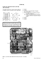
Motor Current Board and C.T.’s:
C.T.’s on the 3
φ
power wiring of each motor send AC
signals proportional to motor current to the Motor Cur-
(YCHA120, 150, 175, 200)
Содержание YCAQ10
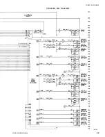
Страница 20: ...YORK INTERNATIONAL 20 LD01779 YCHA100 FIG 9 WIRING DIAGRAM YCHA100...
Страница 21: ...FORM 150 40 NM20 21 YORK INTERNATIONAL YCHA100 LD01779 D...
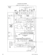
Страница 22: ...YORK INTERNATIONAL 22 LD01780 L YCHA100 FIG 9 Continued...
Страница 23: ...FORM 150 40 NM20 23 YORK INTERNATIONAL LD01780 R YCHA100...
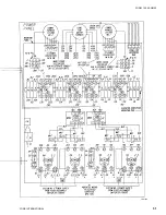
Страница 24: ...YORK INTERNATIONAL 24 YCHA100 LD01781 FIG 9 Continued...
Страница 25: ...FORM 150 40 NM20 25 YORK INTERNATIONAL LD01782 YCHA100...
Страница 46: ...YORK INTERNATIONAL 46 LD01787...
Страница 47: ...FORM 150 40 NM20 47 YORK INTERNATIONAL LD01788...
Страница 48: ...YORK INTERNATIONAL 48 LD01789...
Страница 49: ...FORM 150 40 NM20 49 YORK INTERNATIONAL LD01790...
Страница 50: ...YORK INTERNATIONAL 50 LD01791...
Страница 51: ...FORM 150 40 NM20 51 YORK INTERNATIONAL LD01792...
Страница 77: ......
Страница 78: ......
Страница 79: ......
Страница 80: ......
Страница 81: ......
Страница 82: ......
Страница 83: ......
Страница 84: ......
Страница 85: ......
Страница 86: ......
Страница 87: ......
Страница 88: ......
Страница 89: ......
Страница 90: ......
Страница 91: ......
Страница 92: ......
Страница 93: ......
Страница 94: ......
Страница 95: ......
Страница 96: ......
Страница 97: ......
Страница 98: ......
Страница 99: ......