York YCAQ10 Скачать руководство пользователя страница 18

YORK INTERNATIONAL

18

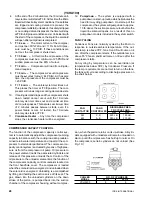
4. LWT Freeze Safety: This analog signal is sent by

the Leaving Chilled Water Sensor. If the tempera-
ture drops to < 36°F(factory setpoint), the system
shuts down. For Brine applications, the setpoint can
be varied from 20°F to 40°F on the Analog Board by
R25. An “F11” code will appear for this safety.

5. LEP (Low Evaporator Pressure Cutout): At run

time = 30 sees to 4 min. the micro checks to see that
suction pressure is 80% cut-out. If not, it shuts the
system down. If the analog signal to the Micro Board
tells the system that the Suction Pressure is low on 3
consecutive starts, the system will shut down and
lock out. See Shutdown Safety Controls, Low Pres-
sure Cutout for trip points. Any time the system shuts
down on a Low Pressure (LP Safety) a 90 min. timer
starts and a “count to 3” counter is software is
incremented to “1”. If the system goes down 2 more
times on a LP Shutdown Safety before the 90 min.
timer times out, the system will shut down and lock
out on a LEP Manual Reset Safety. If the 90 min.
timer times out without 2 more LP shutdowns, the
“count to 3” counter will be cancelled and reset to
“0”. This safety operates like all other Manual Reset
Safeties. An “F3” will be displayed for this cutout.

6. FS (Fault Stop): If external High Discharge Pres-

sure Cutout or external Thermal Motor Overload Sen-
sor contacts open, the system will shut down. The
manual reset on the sensor(if equipped) must be re-
set before the system can be restarted. The external
HP cutout is set at 395 PSI. An F1 will be displayed
for this safety. Note: These same codes will also be
displayed for a Motor Current (power) Fault. This oc-
curs because these safeties do not allow the motor
contactor to energize, causing motor current to be
“0”. When the system is to start, the Micro sends the
start signal to the contactor pilot relay on the Relay
Output Board. The pilot relay closes a contact which
applies 115VAC to the motor contactor. If the High
Pressure C.O. or motor protector opens, their con-
tacts which are wired in series with the pilot relay
contacts keep 115VAC from being applied to the
motor contactor. The contactor will not pull in as the
Micro commands or will drop out if pulled in so the
system will shut down on low motor current. When-
ever an “F1” Fault occurs, check discharge pressure
at the time of the fault, motor current at the time of
fault, and also if the H.P. and motor protector con-
tacts are open.

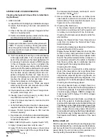
OTHER SAFETY CONTROLS

1. Suction Pressure: If Suction Pressure exceeds 105

PSIG, the Micro Board will unload the compressor. It
will automatically reload when suction pressure drops
below 95 PSIG.

(YCHA100)

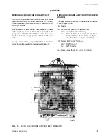
2. Flow Switch: To assure that water flow is present in

the evaporator, the Micro Board senses the Flow
Switch input to the R.P. Relay whose contacts con-
nect to J18 & J 19 of the Analog Input Board. If the
Flow Switch opens, the system will shut down and
will not restart until flow is present. An “A” code will
be displayed. The Flow Switch is connected to ter-
minals 3 & 4 of the terminal block at the bottom right
of the Logic Panel. See Fig. 7.

REMOTE START/STOP BY A TIME CLOCK, BUILD-
ING AUTOMATION, OR ENERGY MANAGEMENT
SYSTEM

Remote starting and stopping is accomplished by open-
ing and closing contacts, controlled by a remote source,
connected to the R.P. Relay. These contacts will be wired
in series with the Flow Switch. The Micro Logic Board
looks for the closure of the contacts as a signal to start
the system. Opening the contacts is a signal to stop the
system. See Fig. 7 for connection points.

Since the remote contacts are wired in series with the
Flow Switch, an “A” code will appear on the display when
a REMOTE STOP command is given (contacts open).
If the optional Digital Input Board is used for Remote
Temperature Setpoint Reset, be sure that remote start
and stop is connected in series with the Flow Switch
and not to the Digital Input Board EMS Start and Stop
inputs. These Start and Stop inputs are not active.

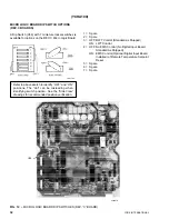
“OPTIONAL” REMOTE TEMPERATURE SETPOINT
RESET

Remote Temperature Setpoint Reset capabilities can
be added by adding an optional Digital Input Board and
configuring a jumper/switch on the Micro Logic Board.
J9 must be IN or Switch #4 must be ON. See Fig. 11
and 12 for jumper/switch location.

Temperature Setpoint changes are accomplished by clos-
ing the contacts between terminals 11 and 12 on the Digi-
tal Input Board for a defined period of time. The lowest
temperature desired must be set on the panel via the
“Return Water Temperature Setpoint” rotary switches. To
change the setpoint, the contacts between terminals 11
and 12 must be closed for a period between 1 and 11
seconds. Closure for a period shorter than 1 second will
be ignored by the Micro Logic Board. Closure longer than
11 seconds will be treated as 11 seconds.

The contact closure corresponds to a positive offset
(rise) from the setpoint on the panel. 1 sec = +0° offset
and 11 sec. = +15° or offset = 1.5 (time closed -1 sec.).
For example: A setpoint of 51° on the panel and a con-
tact closure of 4.33 sec. will result in an offset of +5°.
This raises the RWT setpoint to 56°F.

Содержание YCAQ10

Страница 1: ...MODELS YCAQ10 YCAM12 YCAK14 YCAKI16 YCAG18 YCAR11 YCAN13 YCAL15 YCAJ17 YCAH19 ALSO MODELS YCH100 120 150 175 200 STYLE C 00004TG WITH MICROPROCESSOR CONTROL PANEL WITH G E II 4 EPROM MODEL YCHA100 WI...

Страница 2: ...cable to units built after May 1 1987 which are identified by the later no menclature A description of both nomenclatures is given below Also a cross reference chart of models is pro vided for your co...

Страница 3: ...IN 35 CONDENSER F MAX 130 UNIT COOLER MODEL WATER GPM YCHA MIN MAX 100 120 550 120 120 580 150 120 580 175 150 640 200 200 700 0 F With Optional Low Ambient Kit NOTE The evaporator is protected agains...

Страница 4: ...the top of the unit The area within the clearances shown above and area under the unit must be kept clear of all obstructions that would impede free air flow to the unit In installations where winter...

Страница 5: ...it The area within the clearances shown above and area under the unit must be kept clear of all obstructions that would impede free air flow to the unit In installations where winter operation is inte...

Страница 6: ...14 2 0AWG 172 250 200 480 1 14 2 0AWG 50 380 415 3 50 210 300 200 480 1 14 2 0AWG 210 300 200 480 1 14 2 0AWG 64 346 3 50 230 350 400 480 1 6 300MCM 230 350 400 480 1 6 300MCM 17 200 360 399 600 400...

Страница 7: ...8 600 30 480 119 413 159 4 4 3 2 2 5 7 119 413 159 4 4 3 2 2 5 7 8 8 600 30 480 148 590 197 1 4 3 2 2 6 2 148 590 197 1 4 3 2 2 6 2 8 8 600 30 480 163 700 216 8 4 3 2 2 6 6 163 700 216 8 4 3 2 2 6 6...

Страница 8: ...ead 50 33 17 43 29 14 50 38 25 12 OIL Sys 1 3 3 3 3 3 CHARGE GALS Sys 2 3 3 3 3 CONDENSER DWP 450 PSIG NO OF FANS 30 DlA DIRECT DRIVE 4 7 8 8 8 60 Hz 11 000 11 000 11 000 11 000 11 000 CFM EACH 50 Hz...

Страница 9: ...DIMENSIONS For ground level installations precautions should be taken to protect the unit from tampering by or injury to unauthorized persons Screws on access panels will prevent casual tampering How...

Страница 10: ...1 405 406 404 YCHA175 401 406 405 403 401 403 403 401 YCHA200 404 403 407 405 404 405 407 402 MOUNTING ALUMINUM COIL UNITS ISOLATOR LOCATIONS CHILLER J K L M N P R S MODEL NO TYPE SIZE YCHA100 2 31 2...

Страница 11: ...nto the control panel circuit These field modifications may be made as shown on the WIRING DIAGRAMS MULTIPLE UNITS For increased compressor protection and to reduce power inrush at start up on multipl...

Страница 12: ...er compressor with 3 unloaders and 4 steps of unloading as needed to maintain the desired leaving water temperature UNIT CONTROLS AND OPERATION YCHA100 Concise step by step instructions are printed on...

Страница 13: ...ding to setting 0 7 respectively 3 SYS ON OFF Switch The switch allows the operator to manually turn off the system To operate the system the switch must be in the ON position 4 DATA DISPLAY CODES Ref...

Страница 14: ...nti recycle timer has 8 min left at shutdown Restart can occur in 8 minutes Anti recycle time greater than 2 min ex Anti recycle timer has 1 min left at shutdown Restart can occur in 2 min Anti recycl...

Страница 15: ...r is started as soon as the first Fault occurs If 2 more faults do not occur in the next 90 minutes the counter is reset to 0 After a fault restart cannot be expected until the anti re cycle timer tim...

Страница 16: ...UNDER POWER SUPPLY BOARD R P RELAY RUN PERMISSIVE RELAY RELAY OUTPUT BOARD 41 EMERGENCY 5 STOP 4 CONNECTIONS 3 FOR FLOW SWITCH REMOTE CYCLING DEVICES 13FU 14FU L 2 GND 115VAC POWER FUSES 115VAC POWER...

Страница 17: ...HAT Unit locks out when the ambient temperature is above 130 F Upon a decrease in temperature below 130 F the unit will restart providing the anti recycle timer has timed out and a minimum 2 minute de...

Страница 18: ...TROLS 1 Suction Pressure If Suction Pressure exceeds 105 PSIG the Micro Board will unload the compressor It will automatically reload when suction pressure drops below 95 PSIG YCHA100 2 Flow Switch To...

Страница 19: ...ut Board This port on the bottom right of the Logic Board J6 allows service personnel to obtain a printout of unit con ditions at any time To make use of this option contact YORK Service or Marketing...

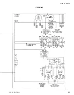
Страница 20: ...YORK INTERNATIONAL 20 LD01779 YCHA100 FIG 9 WIRING DIAGRAM YCHA100...

Страница 21: ...FORM 150 40 NM20 21 YORK INTERNATIONAL YCHA100 LD01779 D...

Страница 22: ...YORK INTERNATIONAL 22 LD01780 L YCHA100 FIG 9 Continued...

Страница 23: ...FORM 150 40 NM20 23 YORK INTERNATIONAL LD01780 R YCHA100...

Страница 24: ...YORK INTERNATIONAL 24 YCHA100 LD01781 FIG 9 Continued...

Страница 25: ...FORM 150 40 NM20 25 YORK INTERNATIONAL LD01782 YCHA100...

Страница 26: ...etween terminals 41 and 2 Should be 115VAC 10 C Assure crankcase heaters are on Allow crank case heaters to remain on a minimum of 24 hours before startup This is important to assure no re frigerant i...

Страница 27: ...he temperature of the liquid refrigerant out of the condenser should not be more than 15 F less than the condensing temperature The temperature corresponding to the condensing pressure from refrigeran...

Страница 28: ...oid opens As a result of this no pumpdown mode is included in the system switch FAN CYCLING Condenser Fans are normally cycled by the Micro in response to outside ambient temperature If the out side t...

Страница 29: ...normal system cycling of the loaders and compressor is experienced due to a cooling range which is too tight Page 30 shows a listing of each cooling range code along with the temperatures at which eac...

Страница 30: ...ING RANGE Loader Stage 2 Setpoint Setpoint minus 0 8 F OF 1 5 F Compressor Stage 1 Setpoint minus 0 7 F Setpoint minus 1 5 F STAGE ON OFF COOLING RANGE Loader Stage 4 Setpoint plus 1 6 F Setpoint plus...

Страница 31: ...e pack 2 of the 7 switches are active An explanation of the Jumpers Switches on the Micro Logic Board is provided on this page and page 32 YCHA100 MICRO LOGIC BOARD JUMPER OPTIONS REV B BOARDS Three j...

Страница 32: ...The dot can be misleading when identifying switch position See the Side View drawings for recommended position verification LD01785 1 Spare 2 Spare 3 OFF RWT Control Standard as Shipped ON LWT Control...

Страница 33: ...n stop valve B Open the discharge stop valve two turns of the stem C Operatethecompressoruntil15to20inchesvacuum is obtained Do this by disconnecting the wiring to LLSV and repeatedly starting the com...

Страница 34: ...ter temp cutout setting ____ F 5 Chilled water setpoint _________________ F 6 Outside Air Temperature _______________ F 7 Low Ambient Temp Cutout Setting _______ F 8 Full load motor current 9 Suction...

Страница 35: ...Check Crankcase Oil heater operation particularly on start up 350 Watt heater should be ON when unit is OFF Measure Heater Current Should be Min 2 Amps 3 Liquid Line Solenoid Valve LLSV 3 Check wirin...

Страница 36: ...fan 130 F Will re start auto rotation matically if temperature 3 Air flow to unit restricted or 3 Check installation clearances drops below 130 F being re circulated See page 4 F10 Fault Code 1 Temper...

Страница 37: ...ctor defective Compressor won t load 1 Suction Pressure 105 PSIG 1 Excessive load Check OPERATING solenoid valve de energizes LIMITATIONS on page 3 Allow unit to to load compressor operate until sucti...

Страница 38: ...uide you through each control and monitoring procedure The control panel is also com patible with a building automation energy management system FIG 13 CONTROL CENTER YCHA 120 200 LD01786 A 4 digit di...

Страница 39: ...selecting 18 of the Select Data Display The mode of failure will then be indicated by a number from 0 11 This number can be translated by comparing the number to the Fault Code listing on the right s...

Страница 40: ...te start up timer has expired since shutdown ex Anti recycle timer has 8 min left at shutdown Restart can occur in 8 minutes Anti recycle time greater than 2 min ex Anti recycle timer has 1 min left a...

Страница 41: ...estart the system The operator should also be aware that be fore the unit will display an F code the prob lem system has already shut down twice on a fault and restarted within the last 90 minutes Thi...

Страница 42: ...2T 13FU 14FU L 2 GND 115VAC POWER FUSES 115VAC POWER INPUT ANALOG INPUT BOARD UNDER POWER SUPPLY BOARD R P RELAY RUN PERMISSIVE RELAY RELAY OUTPUT BOARD 41 EMERGENCY 5 STOP 4 CONNECTIONS 3 FOR FLOW S...

Страница 43: ...mum 2 minute delay has passed An F 10 code will be displayed while the temperature is low and both sys tems will be shut down The F will disappear when temp rises above cut out 5 High Ambient Temperat...

Страница 44: ...ent Whenever an F1 or F5 Fault occurs check discharge pressure at the time of the fault motor current at the time of fault and also if the H P and motor protector contacts are open YCHA120 150 175 200...

Страница 45: ...ANNUNCIATION ALARM CONTACTS OPTIONAL YORK can supply alarm contacts which will de energize to function as a warning if unit malfunction occurs A 28 volt external alarm circuit by others must be wired...

Страница 46: ...YORK INTERNATIONAL 46 LD01787...

Страница 47: ...FORM 150 40 NM20 47 YORK INTERNATIONAL LD01788...

Страница 48: ...YORK INTERNATIONAL 48 LD01789...

Страница 49: ...FORM 150 40 NM20 49 YORK INTERNATIONAL LD01790...

Страница 50: ...YORK INTERNATIONAL 50 LD01791...

Страница 51: ...FORM 150 40 NM20 51 YORK INTERNATIONAL LD01792...

Страница 52: ...measurement between terminals 41 and 2 Should be 115VAC 10 C Assure crankcase heaters are on Allow crank case heaters to remain on a minimum of 24 hours before startup This is important to assure no...

Страница 53: ...erature of the liquid refrigerant out of the condenser should not be more than 15 F less than the condensing temperature The temperature cor responding to the condensing pressure from refrig erant tem...

Страница 54: ...t be cutout cutout 44 PSIG At the same time the oil pressure of the lag compressor must be 20 PSID 14 T 10 min The anti recycle timer times out This places the timer at T 0 position The compressors wi...

Страница 55: ...compres sor capacity control solenoids located on the front handhole cover The compressor is loaded when the solenoid is de energized and unloaded when the sole noid is energized Unloading is accompli...

Страница 56: ...nge 10 System Switches Both ON SYS 1 LEAD J8 on Micro Logic IN or Sw 5 on Micro ON J10 on Micro Logic OUT or Sw 3 on Micro OFF Typical 4 stages of unloading RWT Control Optional 6 or 8 stages of unloa...

Страница 57: ...1 5 F 4 1 6 F 5 1 8 F 6 1 9 F 7 2 0 F LWT COOLING RANGES 6 AND 8 STAGE If the LWT option is utilized loading and unloading for each stage and the respective temperature at which it occurs is shown in...

Страница 58: ...Setpoint minus 0 3 F COOLING RANGE Lead Compr Loader Stage 3 Setpoint minus 0 2 F Setpoint minus 0 7 F OF 1 6 F Lead Compr Loader Stage 2 Setpoint minus 0 5 F Setpoint minus 1 1 F Lead Compressor Stag...

Страница 59: ...t plus 0 7 F Setpoint COOLI NG RANGE Lead Compr Loader Stage 2 Setpoint Setpoint minus 0 7 F OF 1 4 F Lead Compressor Stage 1 Setpoint minus 0 7 F Setpoint minus 1 4 F STAGE ON OFF COOLING RANGE Lag C...

Страница 60: ...e 7 switches are active An explanation of the Jumpers Switches on the Micro Logic Board is provided on this page and page 61 YCHA120 150 175 200 MICRO LOGIC BOARD JUMPER OPTIONS REV B BOARDS Three jum...

Страница 61: ...N EMS Control Optional Digital Input Board Installed 5 OFF 4 Stage Control Standard as Shipped ON 8 Stage Control Optional as ordered for 6 7 or 8 stage control 6 Spare 7 OFF Automatic lead lag compre...

Страница 62: ...the discharge stop valve two turns of the stem C Operate the compressor until 15 to 20 inches vacuum is obtained Do this by disconnecting the wiring to LLSV and repeatedly starting the compres sor Rec...

Страница 63: ...Optional 3 Optional 4 Low leaving water temperature cutout setting __ F 5 Chilled water setpoint ______________ F 6 Outside Air Temperature ___________ F 7 Low Ambient Temp Cutout Setting ___ F 8 Ful...

Страница 64: ...2 Check Crankcase Oil heater operation particularly on start up 350 Watt heater should be ON when unit is OFF Measure Heater Current Should be Min 2 Amps 3 Liquid Line Solenoid Valve LLSV 3 Check wir...

Страница 65: ...p Correct fan Will re start automatically rotation if temperature drops below 130 F 3 Air flow to unit restricted or 3 Check installation clearances See being re circulated page 5 F10 Fault Code 1 Tem...

Страница 66: ...load Check OPERATING solenoid valve System 1 or 95 PSIG System LIMITATIONS on page 3 Allow de energizes to 2 unit to operate until suction pressure load compressor drops to 95 PSIG System 1 or 85 PSIG...

Страница 67: ...on the Micrologic Board to the ON position Right side pushed down This enables manual adjustment of the low ambient cut out 2 Select Display Code 0 7 on the Control Panel to view the low ambient cut...

Страница 68: ...f the fans This modification should be performed as follows 1 Place SW2 on the Micrologic Board to the ON position Right side pushed down This enables manual adjustment of the low ambient cut out 2 Se...

Страница 69: ...to the defective component Enclosed with the new part you will also receive a return address label which must be used when returning the defective part Only defective printed circuit boards are to be...

Страница 70: ...EV 1 D157 031 00928 002 water GE II 4BR REV 0 B8BC 031 00928 005 brine Dual System REV B or C GE II 5 REV 1 B727 031 00928 001 water GE II 5BR REV 0 CID6 031 00928 004 brine If a low ambient kit is in...

Страница 71: ...nal fuse opens in the 2T transformer and can be replaced by simply locating the fuse under the brown paper wrapping carefully slitting the paper and soldering in a new fuse The fuse is a standard 3 4...

Страница 72: ...e the MCB resistor is plugged in See Fig below This will positively determine the line level of MCB you need The line level will be stamped behind the part number 031 00817B i e 031 0081702 The B shou...

Страница 73: ...pr 2 will come on These fans will remain on regardless of discharge pressure or loading until the respective compressor stops or temperature drops below 35 F The other two fans on each system are cycl...

Страница 74: ...CH No Does Not Apply GE Series C YCHA Yes No GE Series C YCHA No Does Not Apply GE Series EFFECTIVE IMMEDIATELY TRANSDUCER WARRANTY REQUIREMENTS FOR RECIP SMART PANEL YORK has made an agreement with K...

Страница 75: ...14 100 75 50 25 CAPACITY Sys 2 100 80 60 20 100 67 50 17 100 71 57 29 100 75 50 25 CONTROL Lead Sys 1 100 80 60 40 20 100 83 67 100 86 71 57 100 88 75 62 OPT Lead 50 33 17 43 29 14 50 38 25 12 Sys 2 1...

Страница 76: ...mpletely and then turn them one turn toward the front seat position to assure that the transducers are not valved off This should also be checked when troubleshooting In the past we have found the cus...

Страница 77: ......

Страница 78: ......

Страница 79: ......

Страница 80: ......

Страница 81: ......

Страница 82: ......

Страница 83: ......

Страница 84: ......

Страница 85: ......

Страница 86: ......

Страница 87: ......

Страница 88: ......

Страница 89: ......

Страница 90: ......

Страница 91: ......

Страница 92: ......

Страница 93: ......

Страница 94: ......

Страница 95: ......

Страница 96: ......

Страница 97: ......

Страница 98: ......

Страница 99: ......

Отзывы: