


YORK INTERNATIONAL
52
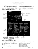
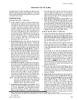
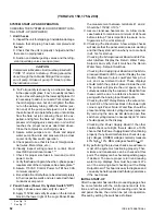
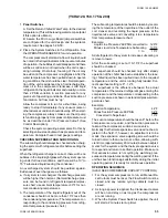
SYSTEM START-UP AND OPERATION
CHECKING THE SYSTEM 24 HOURS PRIOR TO INI-
TIAL START-UP (NO POWER)
1. Unit Checks
A. Inspect the unit for shipping or installation damage.
B. Assure that all piping has been completed and
flushed.
C. Check that the unit is properly charged and that
there are no piping leaks.
D. Suction and discharge stop valves and the refrig-
erant liquid stop valves are open (ccw).
E. “Full” oil quantity is shown by an oil level showing
in the upper sight glass. “Low” oil quantity is shown
by an oil level showing in the lower sight glass. If it
is necessary to add oil, connect a York oil pump to
the oil charging valve, but do not tighten the flare
nut on the delivery tubing. With the bottom (suc-
tion end) of the pump submerged in oil to avoid
the entrance of air, operate the pump until oil drips
from the flare nut joint, allowing the air to be ex-
pelled, and tighten the flare nut. Open the com-
pressor oil charging valve and pump in oil until oil
reaches the proper level as described above.
Close the compressor oil charging valve.
F. Assure water pumps are on. Check and adjust
water pump flow rate and pressure drop across
cooler. Verify flow switch operation.
G. Check panel to see that it is free of foreign mate-
rial (wires, Metal chips, etc.).
H. Visually inspect wiring (power & control). Must
meet NEC and all local codes.*,**
I. Check for proper size fuses in main and control
power circuits.
J. Verify that field wiring matches the 3-phase power
requirements of the compressor. See nameplate.**
K. Assure 115VAC Control Power to TBI has 30A
minimum capacity.*
L. Be certain all control bulbs are inserted completely
in their respective wells and are coated with heat
conductive compound.
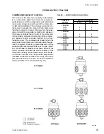
2. Panel Checks (Power On, System Switch “Off”)
A. Apply 3 phase power and verify its value.**
B. Apply 11 5VAC and verify its value on the terminal
block in the lower right of the Logic Panel. Make
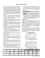
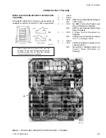
(YCHA120, 150, 175 & 200)
CAUTION
Compressor lubrication circuit must be primed with
YORK “C” oil prior to start-up. Priming should be
done through the Schrader fitting at the compres-
sor oil pump. Stroke oil pump 10 times to prime
the lubrication circuit.
the measurement between terminals 41 and 2.
Should be 115VAC
±
10%.*
C. Assure crankcase heaters are on. Allow crank-
case heaters to remain on a minimum of 24 hours
before startup. This is important to assure no re-
frigerant is in the oil at start-up!
D.
Checking The Electronics A few simple checks
will assure that the panel electronics are working
and that the system will run when you come back
in 24 hrs. for start-up.
Checking the Microprocessor Board and its Par-
allel Interface Display the Return Water Temp.
Setpoint and verify that it matches the Return
Water Temp. Setpoint Switches.
Checking the Analog Input Board and the Micro-
processor Board’s A/D Converter Display the Low
Suction Pressure Cutout, Low Water Temp. Cut-
out, and Low Ambient Cutout. These displays
should match the printout placed inside the unit.
The printout will provide the unit specs. on the
cutouts as ordered by the customer. Deviation from
these could be due to a defective board or tam-
pering with the Analog Input Board pots.
Checking the R.P. Relay Remove the wire on ter-
minal 3 & 4 of the terminal block in the lower right
corner Logic Panel. Note: Water flow should be
present and any remote cycling devices jumpered.
By removing the wire, we simulate an open flow
switch or cycling device. Consequently an “A” code
should appear on the display.
Checking the Power Supply Board If the other
boards check out alright, there is almost a 100%
chance that the Power Supply Board is functioning
properly. If any board malfunctions, check its sup-
ply voltages. UNREG voltages normally measure
40% high + 10%. REG voltages should be + .IV.
E. By performing the previous checks, we will assure
most of the system is functioning properly. Ther-
mistors and transducers can be checked at this
point. The display can be checked against a gauge
if desired. To assure proper return and leaving
water temp. displays, flow must be present. We
won’t be worrying about checking out the Relay
Output Board. This board is easy to diagnose and
can easily be field repaired with factory assistance
if the need arises.
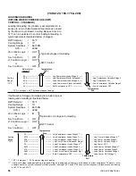
INITIAL START-UP
After the operator has read the proceeding pages, has
be. come familiar with the control panel and its func-
tions, and has performed the proceeding unit checks
and panel checks, the unit can be put into operation.
Proceed by setting the switches as follows:
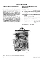
*
See Fig. 16
**
See Fig. 17
Содержание YCAQ10
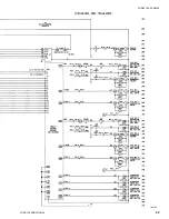
Страница 20: ...YORK INTERNATIONAL 20 LD01779 YCHA100 FIG 9 WIRING DIAGRAM YCHA100...
Страница 21: ...FORM 150 40 NM20 21 YORK INTERNATIONAL YCHA100 LD01779 D...
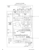
Страница 22: ...YORK INTERNATIONAL 22 LD01780 L YCHA100 FIG 9 Continued...
Страница 23: ...FORM 150 40 NM20 23 YORK INTERNATIONAL LD01780 R YCHA100...
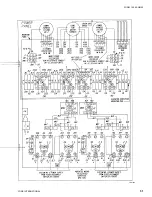
Страница 24: ...YORK INTERNATIONAL 24 YCHA100 LD01781 FIG 9 Continued...
Страница 25: ...FORM 150 40 NM20 25 YORK INTERNATIONAL LD01782 YCHA100...
Страница 46: ...YORK INTERNATIONAL 46 LD01787...
Страница 47: ...FORM 150 40 NM20 47 YORK INTERNATIONAL LD01788...
Страница 48: ...YORK INTERNATIONAL 48 LD01789...
Страница 49: ...FORM 150 40 NM20 49 YORK INTERNATIONAL LD01790...
Страница 50: ...YORK INTERNATIONAL 50 LD01791...
Страница 51: ...FORM 150 40 NM20 51 YORK INTERNATIONAL LD01792...
Страница 77: ......
Страница 78: ......
Страница 79: ......
Страница 80: ......
Страница 81: ......
Страница 82: ......
Страница 83: ......
Страница 84: ......
Страница 85: ......
Страница 86: ......
Страница 87: ......
Страница 88: ......
Страница 89: ......
Страница 90: ......
Страница 91: ......
Страница 92: ......
Страница 93: ......
Страница 94: ......
Страница 95: ......
Страница 96: ......
Страница 97: ......
Страница 98: ......
Страница 99: ......