

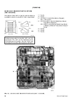


YORK INTERNATIONAL
40
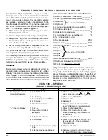
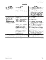
Leftmost Digit: No letter (Blank) – Informs the oper-
ator that both compressors are ready to run or are
running.
A – Indicates that the Flow Switch is open, time clock is
telling the system to turn off, or a remote cycling device
(EMS, BAS. etc.) is telling the system to turn off. These
are devices whose dry contacts may be connected in
series across terminals 3 and 4 of the terminal block in
the lower right corner of the Logic Panel.
c – Shows that System # 1 compressor is shut down and
cycling on the 2-minute start-up or 10-minute anti-
recycle timer. It will be available for start or will restart
when the 2-minute start-up and 10-minute antirecycle
timers time out, and demand allows. Tlle “c” code will
disappear as soon as the timers time out.*
d – Shows that System #2 compressor is shut down
and cycling on the 2-minute start-up or 10-minute
anticycle timer. It will be available for or will restart
when the 2-minute start-up and 10-minute
anti-recycle timers time out, and demand allows.
The “d” will disappear as soon as the timers time
out.*
E – Indicates that both compressors are shut down and
cycling on the 2-minute start-up or 10-minute anti-
recycle timer. Both will be available for or will re-
start when the 2-minute start-up and 10-minute anti-
recycle timers time out, and demand allows. The
“E” code will disappear as soon as the timers tone
out.*
F – Indicates that a safety threshold has been exceeded
and the unit is shut down on a Fault. Turn the Se-
lect Data Display to “18” to determine the reason
for shutdown. (See list at right.)
H – Indicates that both of the compressors are off be-
cause cooling demand is not present. The
compressor(s) will start as soon as cooling demand
is required. The H code will override c, d, or E code.
*Anti-Recycle Timers: Any time a compressor shuts
down for any reason, restart cannot occur until the
10-minute anti-recycle timer has timed out and a mini-
mum of 2 minutes (2 minute start-up timer) has expired
since shutdown.
ex. Anti-recycle timer has 8 min. left at shutdown:
Restart can occur in 8 minutes (Anti-recycle time
greater than 2 min.)
ex. Anti-recycle timer has 1 min. left at shutdown:
Restart can occur in 2 min. (Anti-recycle time less
than 2 min.)
ex. Anti-recycle timer has timed out at shutdown:
Restart can occur in 2 min. (Anti-recycle time less than
2 min.)
ex. Power failure has occurred:
Restart can occur 2 min. after the return of power
(Anti-recycle time less than 2 min.)
Both compressors can never start simultaneously un-
der any condition. A one minute time delay will always
seperate compressor starts.
**FAULT CODES
0. No Fault
1. Micro detected low/hi motor current or
External hi pressure cutout
or
External motor overload
2. Low Oil Pressure, PSID
3. Low suction pressure, PSIG
4. Micro detected high pressure cutout
5. Micro detected low/hi motor current or
External hi pressure cutout
or
External motor overload
6. Low oil pressure, PSID
7. Low suction pressure, PSIG
8. Micro detected high pressure cutout
9. High ambient temperature
10. Low ambient temperature
11. Low water temperature
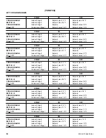
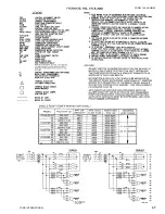
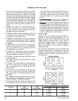
DATA DISPLAY CODES
0. Return chilled water temperature
1. Leaving chilled water temperature
2. Optional
3. Optional
4. Low leaving water temperature cutout setting
5. Chilled water setpoint
6. Outside Air Temperature
7. Low Ambient Temperature
Cutout Setting
8. % Full load motor current
9. Suction pressure, PSIG
10. Oil pressure, PSID
11. Discharge pressure, PSIG
12. % Full load motor current
13. Suction pressure, PSIG
14. Oil pressure, PSID
15. Discharge pressure, PSIG
16. Suction pressure cutout setting, PSIG
17. Optional
18. Fault code (See below) **
This data will be
displayed.
➤
If “Select Data Display”
Switches are set at:
➤
}
System 1
System 2
If F appears in leftmost position
and “Select Data Display” Switches
are set at 18, any of these Fault
Codes may appear:
Description of Fault. (See
Next Page for Diagnosis)
➤
➤
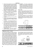
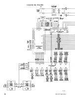
FIG. 14 – DATA DISPLAY
(YCHA120, 150, 175 & 200)
WILL DISPLAY 2 OR 3 DIGITS REPRE-
SENTING DATA AS SELECTED ON
“SELECT DATA DISPLAY SWITCHES”
(SEE FIG. 1 AND LISTS BELOW.)
WILL BE BLANK OR
CONTAIN A LETTER
A, c, d, E, OR H
{
➤
}
}
System 1
System 2
}
Содержание YCAQ10
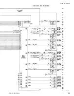
Страница 20: ...YORK INTERNATIONAL 20 LD01779 YCHA100 FIG 9 WIRING DIAGRAM YCHA100...
Страница 21: ...FORM 150 40 NM20 21 YORK INTERNATIONAL YCHA100 LD01779 D...
Страница 22: ...YORK INTERNATIONAL 22 LD01780 L YCHA100 FIG 9 Continued...
Страница 23: ...FORM 150 40 NM20 23 YORK INTERNATIONAL LD01780 R YCHA100...
Страница 24: ...YORK INTERNATIONAL 24 YCHA100 LD01781 FIG 9 Continued...
Страница 25: ...FORM 150 40 NM20 25 YORK INTERNATIONAL LD01782 YCHA100...
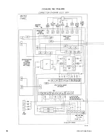
Страница 46: ...YORK INTERNATIONAL 46 LD01787...
Страница 47: ...FORM 150 40 NM20 47 YORK INTERNATIONAL LD01788...
Страница 48: ...YORK INTERNATIONAL 48 LD01789...
Страница 49: ...FORM 150 40 NM20 49 YORK INTERNATIONAL LD01790...
Страница 50: ...YORK INTERNATIONAL 50 LD01791...
Страница 51: ...FORM 150 40 NM20 51 YORK INTERNATIONAL LD01792...
Страница 77: ......
Страница 78: ......
Страница 79: ......
Страница 80: ......
Страница 81: ......
Страница 82: ......
Страница 83: ......
Страница 84: ......
Страница 85: ......
Страница 86: ......
Страница 87: ......
Страница 88: ......
Страница 89: ......
Страница 90: ......
Страница 91: ......
Страница 92: ......
Страница 93: ......
Страница 94: ......
Страница 95: ......
Страница 96: ......
Страница 97: ......
Страница 98: ......
Страница 99: ......