


FORM 150.40-NM20
11
YORK INTERNATIONAL
COMPRESSOR MOUNTING
The compressor(s) are mounted on four (4) isolator pads
(one under each compressor foot). (See Fig. 3.) The
mounting bolts are not to be loosened or adjusted at
installation.
4. All chilled liquid piping should be thoroughly
flushed to free it from foreign material before the
system is placed into operation. Use care not to
flush any foreign material into or through the
cooler.
5. As an aid to servicing, thermometers and pressure
gauges are recommended for installation in the inlet
and outlet water lines. One connection point (plugged)
is provided in each cooler nozzle. Thermometers and
gauges are not furnished with the unit and are to be
furnished by other suppliers.
6. The chilled liquid lines that are exposed to outdoor
ambients should be wrapped with a supplemental
heater cable and insulated to protect against
freeze-up during low ambient periods, and to pre-
vent fomlation of condensation on lines in warm
humid climates.
7. A chilled water flow switch, (either by YORK or oth-
ers) must be installed in the leaving water piping of
the cooler. There should be a straight horizontal run
of at least 5 diameters on each side of the switch.
Adjust the flow switch paddle to the size of pipe in
which it is to be installed. (See: manufacturer’s in-
structions furnished with switch.) The switch is to
be wired to terminals in the control panel as shown
in the WIRING DIAGRAM.
WARNING: Flow switch must not be used to stop
and start chiller.
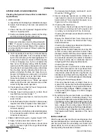
ELECTRICAL WIRING
The YORK Series YCHA Packaged Liquid Chillers are
shipped with all contained controls wired for operation.
Field Wiring – Power wiring must be provided through
a fused disconnect switch. Minimum circuit ampacity
and maximum dual element fuse size are given on page
6. A 115-1-60/ 50, 30 amp source must be supplied for
the control panel through a fused disconnect when a
control panel transformer (optional) is not provided.
Refer to Wiring Diagrams.
Affiliated apparatus, such as a chilled water flow switch,
auxiliary contacts from the chilled water pump starter,
alarms, etc. should be interlocked into the control panel
circuit. These field modifications may be made as shown
on the WIRING DIAGRAMS.
MULTIPLE UNITS
For increased compressor protection and to reduce
power inrush at start-up on multiple chiller installa-
tions, provisions must be made to prevent simulta-
neous start-up of two or more units. Also, some
method must be employed to automatically cycle on
or off one or more of the units to permit more effi-
cient operation at part load conditions. A sequencing
kit may be acquired through your local YORK repre-
sentative.
CHILLED LIQUID PIPING
General – When the unit has been located in its final
position, the unit liquid piping may be connected. Nor-
mal installation precautions should be observed in or-
der to receive maximum operating efficiencies. Piping
should be kept as free as possible of all foreign matter.
All liquid cooler piping must comply in all respects with
local plumbing codes and ordinances.
Since elbows tees and valves decrease pump capacity,
all piping should be kept as simple as possible.
Hand stop valves should be installed in all lines to facili-
tate servicing.
Piping to the inlet and outlet connections of the chiller may
include high-pressure rubber hose or piping loops to in-
sure against transmission of vibration. This is optional and
the necessary components must be obtained in the field.
Drain connections should be provided at all low points
to permit complete drainage of liquid cooler and piping
system.
A small valve or valves should be installed at the high-
est point or points in the chilled liquid piping to allow
any trapped air to be purged. Vent and drain connec-
tions should be extended beyond the insulation to make
them accessible.
The piping to and from the cooler must be designed to
suit the individual installation. It is important that the
following considerations be observed:
1. The chilled liquid piping system should be laid out
so that the circulating pump discharges directly into
the cooler. The suction for this pump should be taken
from the piping system return line and not the cooler.
2. The inlet and outlet cooler liquid connection sizes
are given on pages 4 and 5.
3. It is recommended that a strainer, preferably 40
mesh, be installed in the cooler inlet line just ahead
of the cooler.
00006TG
FIG. 3 – COMPRESSOR MOUNTING PAD
Содержание YCAQ10
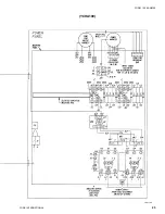
Страница 20: ...YORK INTERNATIONAL 20 LD01779 YCHA100 FIG 9 WIRING DIAGRAM YCHA100...
Страница 21: ...FORM 150 40 NM20 21 YORK INTERNATIONAL YCHA100 LD01779 D...
Страница 22: ...YORK INTERNATIONAL 22 LD01780 L YCHA100 FIG 9 Continued...
Страница 23: ...FORM 150 40 NM20 23 YORK INTERNATIONAL LD01780 R YCHA100...
Страница 24: ...YORK INTERNATIONAL 24 YCHA100 LD01781 FIG 9 Continued...
Страница 25: ...FORM 150 40 NM20 25 YORK INTERNATIONAL LD01782 YCHA100...
Страница 46: ...YORK INTERNATIONAL 46 LD01787...
Страница 47: ...FORM 150 40 NM20 47 YORK INTERNATIONAL LD01788...
Страница 48: ...YORK INTERNATIONAL 48 LD01789...
Страница 49: ...FORM 150 40 NM20 49 YORK INTERNATIONAL LD01790...
Страница 50: ...YORK INTERNATIONAL 50 LD01791...
Страница 51: ...FORM 150 40 NM20 51 YORK INTERNATIONAL LD01792...
Страница 77: ......
Страница 78: ......
Страница 79: ......
Страница 80: ......
Страница 81: ......
Страница 82: ......
Страница 83: ......
Страница 84: ......
Страница 85: ......
Страница 86: ......
Страница 87: ......
Страница 88: ......
Страница 89: ......
Страница 90: ......
Страница 91: ......
Страница 92: ......
Страница 93: ......
Страница 94: ......
Страница 95: ......
Страница 96: ......
Страница 97: ......
Страница 98: ......
Страница 99: ......