94
YORK INTERNATIONAL
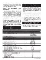
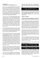
To program the SYSTEM 1 MOTOR CURR, access the
password protected values as described previously. Key
in the current value that equals 100% FLA and press the
ENTER key. The new value will be entered into memory
and the display will advance to the next user
programmable value.
SYSTEM 2 MOTOR CURR
SYSTEM 2 MOTOR CURR allows the operator to display
the approximate current that the motor is drawing by
pressing the Display key labeled % MOTOR CURRENT.
SYSTEM 2 MOTOR CURR also allows the motor current
to be programmed at 100% full load to permit the micro to
determine the approximate slide valve position when
controlling loading/unloading. This is important to allow
load sharing.
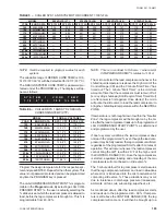
Select the actual current at 100% load by selecting the
chiller model and voltage from Table 2 and its
corresponding AMPS at 100% RLA. Approximate FLA
can be determined by formula: RLA x 1.2 = 100% FLA.
To program the SYSTEM 2 MOTOR CURR, access the
password protected values as described previously. Key
in the current value that equals 100% FLA and press the
ENTER key. The new value will be entered into memory
and the display will advance to the next user
programmable value.
LIQUID INJECTION TEMP LIMIT
LIQUID INJECTION TEMP LIMIT programs the
discharge temperature at which the liquid injection
solenoid is energized to allow liquid to be injected into the
compressor for oil cooling. This assures that temper-
atures of the oil are maintained low enough to assure
proper lubrication and compressor cooling.
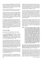
The recommended program point is 180°F (82.1°C).
To program the LIQUID INJECTION TEMP LIMIT,
access the password protected values described
previously. Key in the value and press the ENTER key.
The new value will be entered into memory and the display
will advance to the next programmable value.
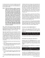
Once on, the liquid injection will turn off 20°F below the
“ON” temperature.
SYSTEM 1 COND TEMP
If loading/unloading is selected utilizing slide valve %, the
design condensing temperature (discharge pressure
converted to temperature or CTP) at 100% load must be
programmed for each system for the specific model of
chiller that is utilized.
To program SYSTEM 1 COND TEMP, access the
password protected values as previously described. Key
in the value for the specific model number from Table 3
and press the ENTER key. The new value will be entered
into memory and the display will advance to the next
programmable option.
NOTE: Proper operation is dependent on proper
programming of this value.
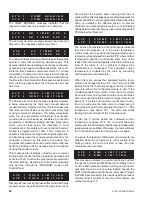
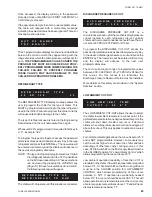
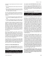
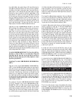
Shown below is an example of this display:
SYSTEM 2 COND TEMP
If loading/unloading is selected utilizing slide valve %, the
design condensing temperature (discharge pressure
converted to temperature or CTP) at 100% load must be
programmed for each system for the specific model of
chiller that is utilized.
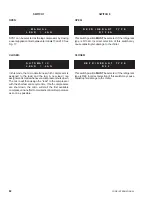
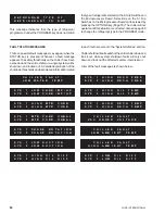
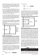
S Y S T E M
2
M O T O R
C U R R
1 8 3
A M P S
=
1 0 0
% F L A
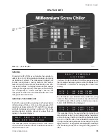
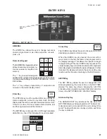
L I Q U I D
I N J E C T I O N
T E M P
L I M I T
=
1 8 0 . 0 ° F
S Y S T E M
1
C O N D
T E M P
1 1 9 . 0
° F
=
1 0 0 %
L O A D
TABLE 2 – CHILLER SYS 1 AND SYS 2 MOTOR CURRENT = 100% FLA
MODEL
200 VOLTS (-17)
230 VOLTS (-28)
460 VOLTS (-46)
575 VOLTS (-58)
YCAS
ENGR. DATA
SYS 1 FLA
SYS 2 FLA SYS 1 FLA
SYS 2 FLA
SYS 1 FLA
SYS 2 FLA
SYS 1 FLA
SYS 2 FLA
140
6A2A2KN6A
338
338
294
294
147
147
118
118
160
6M4M4KN6A
406
406
354
354
176
176
141
141
170
6F5M5NN6A
484
484
421
421
210
210
169
169
180
6F5F5NN6A
484
484
421
421
210
210
169
169
190
6H6F5NN6A
598
484
522
421
259
210
207
169
216
6P7H6NN6A
—
—
—
—
320
259
254
207
236
6P7P7NN6A
—
—
—
—
320
320
254
254
246
6S7S7NN6A
—
—
—
—
320
320
254
254
216x
10H5H5NN6A
—
—
—
—
210
210
169
169
236x
10P6H6NN6A
—
—
—
—
259
259
207
207
266x
10S7S7NN6A
—
—
—
—
320
320
254
254
Содержание Millennium YCAS 216X
Страница 11: ...FORM 201 10 NM1 11 YORK INTERNATIONAL YCAS 140 246 DIMENSIONS English LD01444 LD01446...
Страница 13: ...FORM 201 10 NM1 13 YORK INTERNATIONAL YCAS 140 246 DIMENSIONS SI LD01440 LD01442...
Страница 15: ...FORM 201 10 NM1 15 YORK INTERNATIONAL YCAS 216X 266X DIMENSIONS English LD01454 LD01454...
Страница 17: ...FORM 201 10 NM1 17 YORK INTERNATIONAL YCAS 216X 266X DIMENSIONS SI LD01450 LD01448...
Страница 33: ...FORM 201 10 NM1 33 YORK INTERNATIONAL 28514A FILTER DRYER LIQUID STOP VALVE...
Страница 37: ...FORM 201 10 NM1 37 YORK INTERNATIONAL LD01285 FIG 3 SCREW CHILLER REFIGERANT FLOW DIAGRAM...
Страница 54: ...54 YORK INTERNATIONAL FIG 9 SYSTEM WIRING YCAS 140 246 CONNECTION DIAGRAM SYSTEM WIRING LD01466 D...
Страница 59: ...FORM 201 10 NM1 59 YORK INTERNATIONAL FIG 11 CONTINUED LD01465 D...
Страница 60: ...60 YORK INTERNATIONAL FIG 12 CONNECTION DIAGRAM WYE DELTA YCAS 140 246 CONNECTION DIAGRAM WYE DELTA LD01458 D...
Страница 61: ...FORM 201 10 NM1 61 YORK INTERNATIONAL FIG 12 CONTINUED LD01458 D...
Страница 69: ...FORM 201 10 NM1 69 YORK INTERNATIONAL FIG 16 CONTINUED LD01206 D...
Страница 71: ...FORM 201 10 NM1 71 YORK INTERNATIONAL FIG 17 CONTINUED LD01202 D...


