FORM 201.10-NM1
105
YORK INTERNATIONAL
ing a high slide valve percentage. 99% would be recom-
mended for absolute minimum cycling. If due to system
conditions, the lead compressor does not reach the pro-
grammed %, even though the lead compressor is fully
loaded, the lag compressor will start regardless of the
programmed % after 5 minutes of operation. This will
occur whenever the lead compressor cannot bring the
leaving chilled liquid within 2.0°F of the high end of the
CONTROL RANGE (CR). Once the lag compressor is
started, equalized loading and unloading will occur as
previously described. This assures that the chiller will
fully load and maintain chilled liquid temperature.
Selecting a LAG COMPRESSOR START % less than
99% increases the efficiency of the chiller. At lower per-
centages, the lead compressor is loaded to the pro-
grammed % and the lag compressor is started and
brought up to a % slide valve equal to the lead compres-
sor. At this point the loading of both compressors is ad-
justed up or down to maintain capacity and equalize load-
ing. Running both compressors partially loaded makes
more efficient use of the evaporator bundle than running
one compressor fully loaded with the other idle. This as-
sures that the entire evaporator is being utilized and
maximum chiller efficiency is achieved. However, keep
in mind that as more capacity is required, the lag com-
pressor will start regardless of the programmed % and
equalized loading at part load will still be achieved, even
with a programmed % of 99%.
If a LAG COMPRESSOR START % of less than 99% is
desired, a value of 70% is recommended. This will
typically assure that the lag compressor will start
before the lead compressor is fully loaded in most
operating conditions.
Selecting The LAG COMPRESSOR DIFFERENTIAL
OFF %
Selection of the LAG COMPRESSOR DIFFERENTIAL
OFF % under the PROGRAM key allows the operator to
select the range over which the lead and lag compressor
load shares equally. This affects the loading sequence at
low loads. Once the lag compressor is brought on and
loads up to a % Slide Valve equal to the lead compres-
sor, load sharing of the compressor will begin. Load shar-
ing will continue until loading of the compressor drops to
the programmed differential % below the LAG COMPRES-
SOR START POINT %.
For example: If a LAG COMPRESSOR START POINT
of 70% is selected, and a LAG COMPRESSOR DIF-
FERENTIAL OFF % of 50% is selected, the lead and lag
compressor will both load share until the % Slide Valve
of the lead compressor drops to 20% (70% - 50% = 20%).
At this point, the micro will unload only the lag compres-
sor until it reaches a point at which the micro determines
it is fully unloaded and the load does not require its con-
tinued operation. The micro will then cycle the lag com-
pressor off. It will also cycle off as described previously,
if the micro determines that chilled liquid temperature is
dropping too low.
The larger the differential programmed, the more efficient
the use of the evaporator. For efficiency purposes, 50%
is recommended. Cycling of the lag compressor will also
be minimized since equalized unloading operates for a
longer period of the loading/unloading scheme.
A small % differential will increase cycling and lower ef-
ficiency slightly. For example: If 10% LAG COMPRES-
SOR DIFFERENTIAL OFF % is selected with a LAG
COMPRESSOR START POINT % of 70%, the lag com-
pressor will start when the lead % FLA reaches 70%.
The lag loading will be brought up to equalize the lead of
70% if demand requires. Both compressors will increase
in loading proportionately as demand increases. When
the load drops, both compressors will unload to 60% (70%
- 10% = 60%). At this point, only the lag compressor will
be unloaded as demand decreases. It will unload to a
point at which the micro determines it is fully unloaded. If
load does not require its continued operation, the com-
pressor will cycle off.
A minimum % FLA point is built into the micro to only
allow load sharing to operate to a minimum of 20% Slide
Valve % of the lead compressor. Therefore, the LAG
COMPRESSOR START % MINUS THE LAG COMPRES-
SOR DIFFERENTIAL OFF % cannot be less than 20%
or an OUT OF RANGE message will appear.
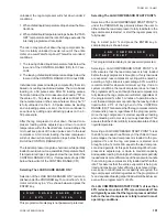
To program the LAG COMPRESSOR DIFFERENTIAL
OFF % under the PROGRAM key, key in the desired
value and press the ENTER key. The new value will be
entered into memory. This value is not password protected
and can be programmed anytime the PROGRAM key is
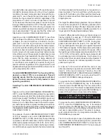
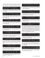
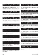
pressed. Shown below is an example of the display:
To program the LAG COMPRESSOR DIFFERENTIAL
OFF % under the PROGRAM key, key in the desired
value and press the ENTER key. The new value will be
entered into memory and the display will advance to the
next user programmable value. This value is not pass-
word protected and can be programmed anytime the
PROGRAM key is pressed.
The micro will accept a range of programmable values
between 0 - 50% for this operating control, provided the
LAG COMPRESSOR START POINT % minus the LAG
COMPRESSOR DIFFERENTIAL OFF % does not equal
less than 20%.
L A G
C O M P R E S S O R
D
I F F E R E N T I A L
O F F
5 0 %
Содержание Millennium YCAS 216X
Страница 11: ...FORM 201 10 NM1 11 YORK INTERNATIONAL YCAS 140 246 DIMENSIONS English LD01444 LD01446...
Страница 13: ...FORM 201 10 NM1 13 YORK INTERNATIONAL YCAS 140 246 DIMENSIONS SI LD01440 LD01442...
Страница 15: ...FORM 201 10 NM1 15 YORK INTERNATIONAL YCAS 216X 266X DIMENSIONS English LD01454 LD01454...
Страница 17: ...FORM 201 10 NM1 17 YORK INTERNATIONAL YCAS 216X 266X DIMENSIONS SI LD01450 LD01448...
Страница 33: ...FORM 201 10 NM1 33 YORK INTERNATIONAL 28514A FILTER DRYER LIQUID STOP VALVE...
Страница 37: ...FORM 201 10 NM1 37 YORK INTERNATIONAL LD01285 FIG 3 SCREW CHILLER REFIGERANT FLOW DIAGRAM...
Страница 54: ...54 YORK INTERNATIONAL FIG 9 SYSTEM WIRING YCAS 140 246 CONNECTION DIAGRAM SYSTEM WIRING LD01466 D...
Страница 59: ...FORM 201 10 NM1 59 YORK INTERNATIONAL FIG 11 CONTINUED LD01465 D...
Страница 60: ...60 YORK INTERNATIONAL FIG 12 CONNECTION DIAGRAM WYE DELTA YCAS 140 246 CONNECTION DIAGRAM WYE DELTA LD01458 D...
Страница 61: ...FORM 201 10 NM1 61 YORK INTERNATIONAL FIG 12 CONTINUED LD01458 D...
Страница 69: ...FORM 201 10 NM1 69 YORK INTERNATIONAL FIG 16 CONTINUED LD01206 D...
Страница 71: ...FORM 201 10 NM1 71 YORK INTERNATIONAL FIG 17 CONTINUED LD01202 D...

