


FORM 201.10-NM1
131
YORK INTERNATIONAL
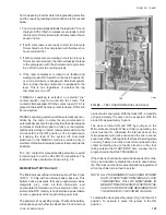
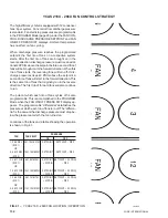
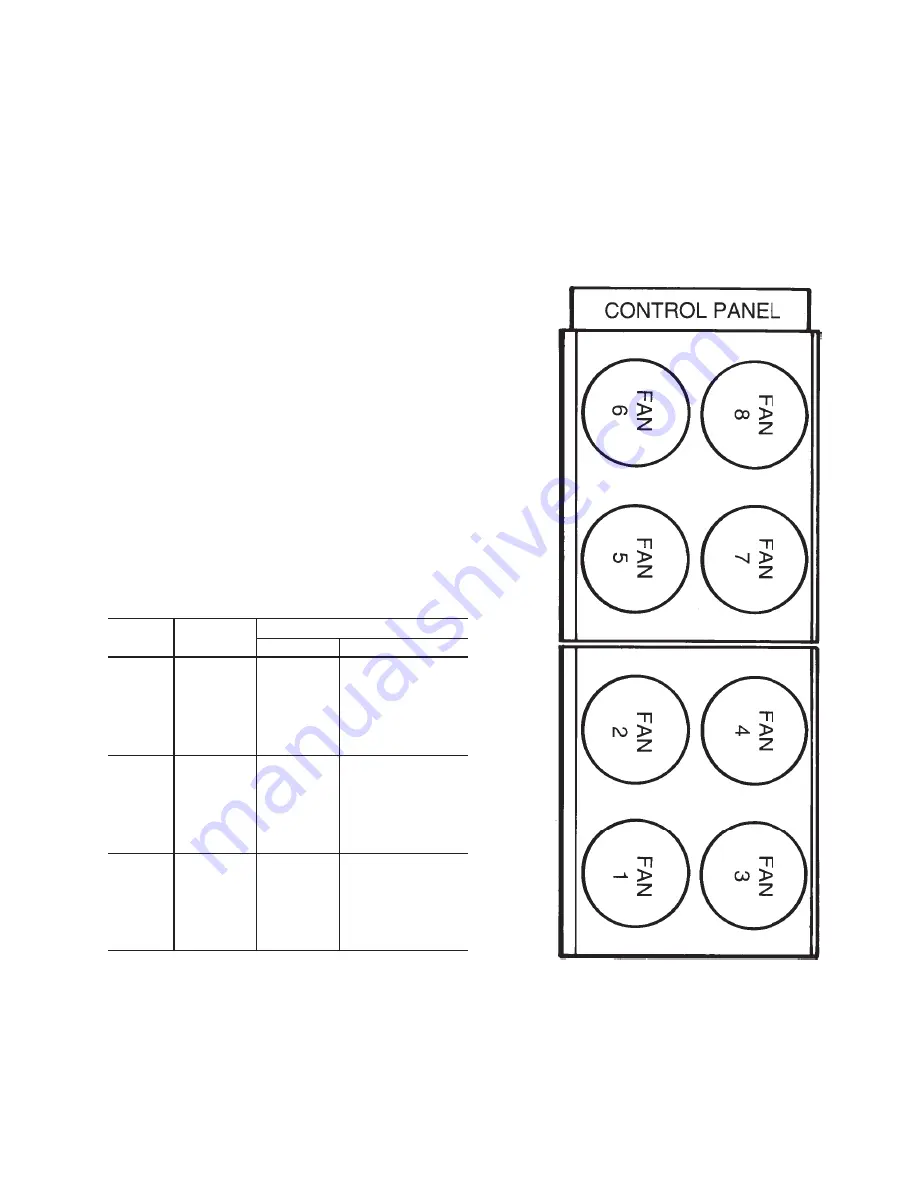
The standard efficiency chiller is equipped with 8 con-
denser fans; 4 per system. Fan control from discharge
pressure is standard. Fan start/stop pressures are pro-
grammable in the PROGRAM Mode (page 93) under the
FAN CONTROL DISCHARGE PRESSURE SETPOINT
and FAN ON/OFF PRESS DIFF displays. Ambient tem-
perature has no effect on fan cycling.
When discharge pressure reaches the programmed
setpoint, the first pair of fans on a respective system
starts. After the first pair of fans are brought on in the
reverse direction, discharge pressure must rise an addi-
tional 20 PSIG above the setpoint before a second pair
of fans will be brought on in the forward direction. When
this pair of fans starts, the reversing fans will turn off. If
discharge pressures rises 40 PSIG above the setpoint,
a second pair of fans will start in the forward direction.
This is the same pair of fans that originally ran in the
reverse direction. The first pair of forward fans will also
continue to run.
The point at which each pair of fans cycles off is also
programmable. This is accomplished in the PROGRAM
Mode when the FAN ON/OFF PRESS DIFF display ap-
pears. The programmable “differential” establishes the
FAN
FAN RELAY
PRESSURE
ON
OFF
1 & 2 REV
9M & 10M
SETPOINT
SETPOINT – DIFF.
(SYS 1)
OR
5 & 6 REV
15M & 16M
SETPOINT
SETPOINT – DIFF.
(SYS 2)
3 & 4 FOR
6M & 8M
SETPOINT
(SE 20 PSIG)
(SYS 1)
+ 20 PSIG
– DIFF
OR
7 & 8 FOR
12M & 14M
SETPOINT
(SE 20 PSIG)
(SYS 2)
+ 20 PSIG
– DIFF
1 & 2 FOR
5M & 7M
SETPOINT
(SE 40 PSIG)
(SYS 1)
+ 40 PSIG
– DIFF
OR
5 & 6 FOR
11M & 13M
SETPOINT
(SE 40 PSIG)
(SYS 2)
+ 40 PSIG
– DIFF
YCAS 140 - 246 FAN CONTROL STRATEGY
pressure at which each pair of fans turn off. The “differ-
ential” is the amount the discharge pressure must drop
below the pressure at which the fan turned on.
Locations of the fans and a table showing the operation
is shown in Fig. 40.
FIG. 40 – YCAS 140 - 246 FAN LOCATION / OPERATION
LD01267
Содержание Millennium YCAS 216X
Страница 11: ...FORM 201 10 NM1 11 YORK INTERNATIONAL YCAS 140 246 DIMENSIONS English LD01444 LD01446...
Страница 13: ...FORM 201 10 NM1 13 YORK INTERNATIONAL YCAS 140 246 DIMENSIONS SI LD01440 LD01442...
Страница 15: ...FORM 201 10 NM1 15 YORK INTERNATIONAL YCAS 216X 266X DIMENSIONS English LD01454 LD01454...
Страница 17: ...FORM 201 10 NM1 17 YORK INTERNATIONAL YCAS 216X 266X DIMENSIONS SI LD01450 LD01448...
Страница 33: ...FORM 201 10 NM1 33 YORK INTERNATIONAL 28514A FILTER DRYER LIQUID STOP VALVE...
Страница 37: ...FORM 201 10 NM1 37 YORK INTERNATIONAL LD01285 FIG 3 SCREW CHILLER REFIGERANT FLOW DIAGRAM...
Страница 54: ...54 YORK INTERNATIONAL FIG 9 SYSTEM WIRING YCAS 140 246 CONNECTION DIAGRAM SYSTEM WIRING LD01466 D...
Страница 59: ...FORM 201 10 NM1 59 YORK INTERNATIONAL FIG 11 CONTINUED LD01465 D...
Страница 60: ...60 YORK INTERNATIONAL FIG 12 CONNECTION DIAGRAM WYE DELTA YCAS 140 246 CONNECTION DIAGRAM WYE DELTA LD01458 D...
Страница 61: ...FORM 201 10 NM1 61 YORK INTERNATIONAL FIG 12 CONTINUED LD01458 D...
Страница 69: ...FORM 201 10 NM1 69 YORK INTERNATIONAL FIG 16 CONTINUED LD01206 D...
Страница 71: ...FORM 201 10 NM1 71 YORK INTERNATIONAL FIG 17 CONTINUED LD01202 D...


