FORM 201.10-NM1
39
YORK INTERNATIONAL
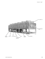
CONDENSER
The air cooled condenser coils use state-of-the-art
louvered fins for heat transfer. Eight fans move air through
the coils. Design working pressure of the condenser is
450 PSIG.
ECONOMIZER
A plate and frame heat exchanger (Economizer) is
installed in the high side of each system for subcooling of
the primary refrigerant liquid to the evaporator. This
increases the efficiency of the system.
The wet vapor to the economizer is supplied by a small 15
ton TXV set for 10°F superheat that flashes off 10 - 20%
of the liquid from the condenser. 10 - 12 tons are utilized
for subcooling liquid refrigerant and 2-3 tons for motor
cooling. The wet vapor for motor cooling is at an
intermediate pressure between discharge and suction
and therefore requires little energy to pump it back through
the compressor to condenser pressure. This results in a
very small loss to system efficiency.
The economizer provides approximately 20°F of
additional subcooling (15°F in, 35°F out) to the liquid
refrigerant which flows to the evaporator at 95° ambient,
55°F RWT, 44°F LWT. Subcooling will drop to approx-
imately 0°F below 90°F ambient. The subcooled liquid is
then fed to the primary TXV in the system. This additional
subcooling results in a significant increase in the
efficiency of the system. The design working pressure of
the economizer is 450 PSIG. The economizer liquid
supply solenoid is activated on start-up coincident with
the liquid line solenoid, after pumpdown.
OIL SEPARATOR / SYSTEM
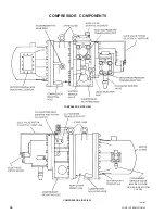
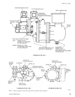
The external oil separator, with no moving parts and
designed for minimum oil carry-over, is mounted in the
discharge line of the compressor. The high pressure
discharge gas is forced around a 90 degree bend and
through centrifugal action, oil is forced to the outside of
the separator and captured on wire mesh where it drains
to the bottom of the oil separator and into the compressor.
The oil (YORK “E” oil - used for R-22 applications), which
drains back into the compressor through a replaceable 0.5
- 3.0 micron oil filter, and oil supply solenoid (energized
when the compressor starts), is at high pressure. This
high pressure “oil injection” forces the oil into the
compressor where it is gravity fed to the gears and
bearings for lubrication. After lubricating the gears and
bearings, it is injected through orifices on a closed thread
near the suction end of the rotors. The oil is automatically
injected because of the pressure difference between
discharge pressure and the reduced pressure at the
suction end of the rotors. This lubricates the rotors as well
as provides an oil seal against leakage around the rotors
to assure refrigerant compression (volumetric efficiency).
The oil also provides cooling by transferring much of the
heat of compression from the gas to the oil keeping
discharge temperatures down and reducing the chance
for oil breakdown. Oil injected into the rotor cage flows into
the rotors at a point about 1.2x suction. This assures that
a required minimum differential of at least 30 PSID exists
between discharge and 1.2x suction, to force oil into rotor
case, a minimum 10 PSI differential is all that is required
to assure protection of the compressor. Oil pressure is
measured as the difference between discharge pressure
and the pressure of the oil entering the rotor case.
Maximum working pressure of the oil separator is 450
PSIG. A relief valve is installed in the oil separator piping.
This will soon be incorporated into the oil separator. Oil
level should be above the midpoint of the “lower” oil sight
glass when the compressor is running. Oil level should not
be above the top of the “upper” sight glass.
Oil temperature control is provided through liquid injection
activated by the microprocessor, utilizing a discharge
temperature sensor, and a solenoid valve.
OIL COOLING / LIQUID INJECTION SYSTEM
A liquid injection system is utilized to maintain oil
temperature and proper oil viscosity. Liquid injection is
controlled by the microprocessor on a demand basis to
provide stable oil, discharge, and motor temperature
control. Liquid injection is fed directly into the motor cover
along with the economizer wet vapor.
A discharge temperature sensor on the compressor
sends an analog signal to the microprocessor to allow the
micro to monitor oil temperature. The micro in turn
controls a solenoid which injects liquid whenever the
discharge temperature rises above 180°F and turns it off
when temperature falls to 160°F. In most circumstances,
liquid injection will not energize during part load operation.
CAPACITY CONTROL
The function of the compressor capacity control system
is to automatically adjust the pumping capacity of the
compressor to satisfy the cooling load to regulate leaving
water temperature (LWT) within the programmed Control
Range (CR). Capacity control is accomplished by moving
a slide valve with a series of load and unload pulses which
changes the entrance point of the suction gas entering the
rotors. This allows refrigerant gas to be injected at
virtually any point on the rotors, keeping in mind that a
minimum capacity of 20% load per compressor (10% total
chiller) is maintained on a compressor for oil return. The
micro also attempts to sequence compressor loading to
maximize efficiency and minimize compressor cycling.
Movement of the slide valve is accomplished by forcing
pressurized oil against a piston which drives the slide
Содержание Millennium YCAS 216X
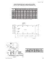
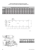
Страница 11: ...FORM 201 10 NM1 11 YORK INTERNATIONAL YCAS 140 246 DIMENSIONS English LD01444 LD01446...
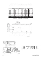
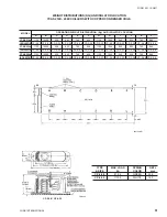
Страница 13: ...FORM 201 10 NM1 13 YORK INTERNATIONAL YCAS 140 246 DIMENSIONS SI LD01440 LD01442...
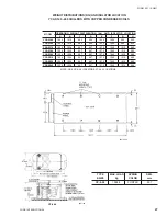
Страница 15: ...FORM 201 10 NM1 15 YORK INTERNATIONAL YCAS 216X 266X DIMENSIONS English LD01454 LD01454...
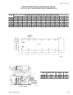
Страница 17: ...FORM 201 10 NM1 17 YORK INTERNATIONAL YCAS 216X 266X DIMENSIONS SI LD01450 LD01448...
Страница 33: ...FORM 201 10 NM1 33 YORK INTERNATIONAL 28514A FILTER DRYER LIQUID STOP VALVE...
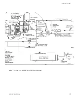
Страница 37: ...FORM 201 10 NM1 37 YORK INTERNATIONAL LD01285 FIG 3 SCREW CHILLER REFIGERANT FLOW DIAGRAM...
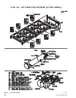
Страница 54: ...54 YORK INTERNATIONAL FIG 9 SYSTEM WIRING YCAS 140 246 CONNECTION DIAGRAM SYSTEM WIRING LD01466 D...
Страница 59: ...FORM 201 10 NM1 59 YORK INTERNATIONAL FIG 11 CONTINUED LD01465 D...
Страница 60: ...60 YORK INTERNATIONAL FIG 12 CONNECTION DIAGRAM WYE DELTA YCAS 140 246 CONNECTION DIAGRAM WYE DELTA LD01458 D...
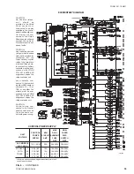
Страница 61: ...FORM 201 10 NM1 61 YORK INTERNATIONAL FIG 12 CONTINUED LD01458 D...
Страница 69: ...FORM 201 10 NM1 69 YORK INTERNATIONAL FIG 16 CONTINUED LD01206 D...
Страница 71: ...FORM 201 10 NM1 71 YORK INTERNATIONAL FIG 17 CONTINUED LD01202 D...

