104
YORK INTERNATIONAL
% slide valve equal to the lead compressor provided
demand dictates. At this point, the loading of both com-
pressors will be adjusted up or down to maintain capac-
ity and equalize loading.
NOTE: Under most operating conditions, viewing %
slide valve of each compressor will show a
difference in the % slide valve of each com-
pressor which at times may be significant.
This condition will exist even though equal-
ized loading / unloading should be observed.
This is due to the micro constantly pulsing
slide valves of each compressor to control
temperature and differences in operating con-
ditions of the two compressors, such as dis-
charge pressure which causes each
compressor’s slide valve to move a different
amount with a pulse of a specific duration.
Other factors such as tolerances in discharge
pressure transducers and mechanical toler-
ances within compressors will also contrib-
ute to differences. Regardless of the differ-
ences in % slide valve, the micro will still
assure that leaving chilled liquid temperature
is properly controlled.
Also, in some cases, the micro will not be programmed
to attempt to control equalized unloading over the entire
loading range which will affect the unloading sequence
slightly. Refer to page 105, “Selecting The LAG COM-
PRESSOR DIFFERENTIAL OFF %” for details.
Approximate loading time for each compressor on a hot
water start is about 5 minutes per compressor at worst
case conditions. If the load drops, both compressors will
each unload equally to a point as determined by the LAG
COMPRESSOR DIFFERENTIAL OFF %. When further
capacity reduction is required, the lag compressor will
continue to unload, and shutdown while the lead com-
pressor maintains its % slide valve loading point. When
fully unloaded, the lag compressor will shut down under
2 conditions:
1. When chilled liquid temperature drops below the Neu-
tral Zone.
2. When chilled liquid temperature drops below the “TAR-
GET” temperature and the rate of change exceeds the
internally programmed rate limits.
The micro may also shut down the lag compressor be-
fore it is totally unloaded to avoid cut-out of the entire
chiller on a Low Water Temp Fault. This will occur under 2
conditions:
1. The leaving chilled liquid temperature falls below the
low end of the CONTROL RANGE (CR) for 37 sec-
onds.
2. The leaving chilled liquid temperature drops below the
low end of the CONTROL RANGE (CR) minus CR/4.
Individual compressor loading is also computed by the
micro based on counting load/unload pulses. The micro
bases loading on a 50 pulse scale, after 50 loading pulses
from total unload, the micro assumes full load at “50” on
the scale of 0 - 50 pulses. Unload pulses subtract from
the numerical value on the scale, whatever it may be. “0”
is fully unloaded on the 0 - 50 pulse scale. As loading
and unloading pulses are sent, the micro continues to
keep track by adding and subtracting pulses on the 0 -
50 pulse scale.
After the lag compressor is shut down, the lead com-
pressor loading will be adjusted up or down to control
temperature within the Neutral Zone. As load drops, the
micro will keep track of the load pulses sent to the lead
compressor. At minimum loading, the lead compressor
will shut down when temperature drops below the low
limit of the CONTROL RANGE (CR).
The lead compressor may also shut down while partially
loaded to avoid cut-out on a Low Water Temperature Fault,
if temperature drops 2 degrees below the low limit of the
CONTROL RANGE (CR) or if temperature drops CR/2
below the low limit of the CONTROL RANGE (CR).
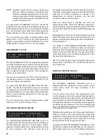
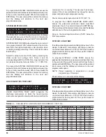
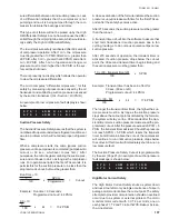
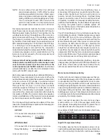
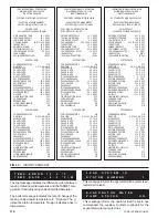
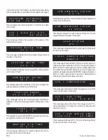
Selecting The LOAD SHARE BASED ON ?
Selection of the LOAD SHARE BASED ON ? can be
made under the PROGRAM key. To control from slide
valve %, key in a “1” as shown below and press the
ENTER key.
This programmable display is not password protected.
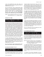
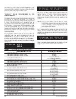
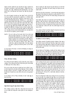
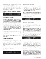
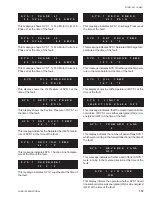
Selecting The Lag Compressor Start Point %
Selection of the LAG COMPRESSOR START % under
the PROGRAM key primarily allows the user to either
allow the lead compressor to fully load before the lag
compressor is started, or start the lag compressor fully
loaded.
Key in a start % and press ENTER key. A sample dis-
play is shown below:
This programmable display is not password protected.
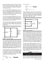
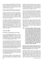
Selecting a LAG COMPRESSOR START % of 99% as-
sures that the lead compressor is fully loaded before the
lag compressor is brought on. If very low loads are ex-
pected, less compressor cycling will be noted by select-
L O A D
S H A R E
B A S E D
O N ?
1
=
S V % ,
2
=
%
F L A
1
L A G
C O M P R E S S O R
S T A R T
P O I N T
7 0 %
Содержание Millennium YCAS 216X
Страница 11: ...FORM 201 10 NM1 11 YORK INTERNATIONAL YCAS 140 246 DIMENSIONS English LD01444 LD01446...
Страница 13: ...FORM 201 10 NM1 13 YORK INTERNATIONAL YCAS 140 246 DIMENSIONS SI LD01440 LD01442...
Страница 15: ...FORM 201 10 NM1 15 YORK INTERNATIONAL YCAS 216X 266X DIMENSIONS English LD01454 LD01454...
Страница 17: ...FORM 201 10 NM1 17 YORK INTERNATIONAL YCAS 216X 266X DIMENSIONS SI LD01450 LD01448...
Страница 33: ...FORM 201 10 NM1 33 YORK INTERNATIONAL 28514A FILTER DRYER LIQUID STOP VALVE...
Страница 37: ...FORM 201 10 NM1 37 YORK INTERNATIONAL LD01285 FIG 3 SCREW CHILLER REFIGERANT FLOW DIAGRAM...
Страница 54: ...54 YORK INTERNATIONAL FIG 9 SYSTEM WIRING YCAS 140 246 CONNECTION DIAGRAM SYSTEM WIRING LD01466 D...
Страница 59: ...FORM 201 10 NM1 59 YORK INTERNATIONAL FIG 11 CONTINUED LD01465 D...
Страница 60: ...60 YORK INTERNATIONAL FIG 12 CONNECTION DIAGRAM WYE DELTA YCAS 140 246 CONNECTION DIAGRAM WYE DELTA LD01458 D...
Страница 61: ...FORM 201 10 NM1 61 YORK INTERNATIONAL FIG 12 CONTINUED LD01458 D...
Страница 69: ...FORM 201 10 NM1 69 YORK INTERNATIONAL FIG 16 CONTINUED LD01206 D...
Страница 71: ...FORM 201 10 NM1 71 YORK INTERNATIONAL FIG 17 CONTINUED LD01202 D...

