


FORM 201.10-NM1
127
YORK INTERNATIONAL
from happening. Factors determining lead/lag selection
and the resulting lead/lag determination are discussed
below:
1. The micro automatically defaults the lead to SYS 1 and
the lag to SYS 2 if both compressors are ready to start
(Anti-recycle Timers timed out) and compressors have
equal run time.
2. If both compressors are ready to start (Anti-recycle
Timers timed out), the compressor with the lowest run
hours will start first.
3. If both compressors are waiting to start (Anti-recycle
Timers are not timed out), the micro will assign the lead
to the compressor with the shortest anti-recycle time
in an effort to provide cooling quickly.
4. If the lead compressor is locked out, faulted and
waiting to restart, SYS switch on the micro board is off,
or a run permissive is keeping an individual system
from running, the lag compressor is swapped to the
lead. This is true regardless of whether the lag
compressor is on or off.
If MANUAL Lead/Lag is selected, an external “dry”
contact (switch) must be wired into the chiller. This
contact is field supplied. With the contact open, SYS 1 is
placed in the lead. When the contact is closed, SYS 2 will
be lead system.
MANUAL Lead/Lag selection will be automatically over-
ridden by the micro to allow the lag compressor to
automatically become the lead anytime the selected lead
compressor shuts down due to a lock-out, lead system
faults and is waiting to restart, lead system switch on the
micro board is in the OFF position, or if a run permissive
is keeping the lead of the system off. Automatic
switchover in the MANUAL mode is provided to try to
maintain chilled liquid temperature as close to setpoint as
possible.
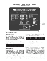
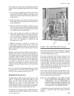
The “dry” contact for manual lead/lag selection is wired
into terminals 13 and 19 of the TB3 Terminal Block. The
location of these contacts is shown in Fig. 38.
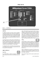
MEMORY BATTERY BACK-UP
The Microprocessor Board contains a Real Time Clock
(RTC) I. C. Chip with an internal battery back-up. This
battery back-up assures that any programmed values
(setpoints, etc.), clock, all fault information, and
accumulated information such as starts/run time, etc.
stored in the RTC memory is not lost when a power failure
occurs, regardless of the length of the power loss.
The battery is a 10 year lithium type. The life of the battery
will depend upon whether the Real Time Clock’s internal
clock circuit is energized. With the clock OFF, a rated life
of approximately 10 years can be expected. With the
clock ON, approximately 5 years.
The clock is turned ON and OFF by a jumper on the
Microprocessor Board. While a chiller is operating, the
clock must be ON. Otherwise the internal clock on the
microprocessor will not be active and the micro cannot
keep track of time, although all other functions will operate
normally. Failure to turn the Clock ON could result in the
chiller not starting due to the time frozen on the clock
falling outside the START/STOP time window that is
programmed in the DAILY SCHEDULE.
If the chiller is shut down for extended periods of months,
it may be desirable to disable the clock to save battery
life. The clock can then be reactivated and reprogrammed
when the chiller is returned to service.
NOTE: ALL PROGRAMMED VALUES AND STORED
DATA, OTHER THAN THE INTERNAL CLOCK
TIME-KEEPING, WILL BE MAINTAINED IN
MEMORY REGARDLESS OF WHETHER THE
CLOCK IS ON OR OFF AND REGARDLESS OF
THE LENGTH OF THE POWER FAILURE.
To disable the clock, place the jumper (Fig. 39) in the OFF
position. To activate it, place the jumper in the ON
position.
FIG. 38 – TB3 LOCATION MANUAL LEAD LAG
27962A
TB3
Содержание Millennium YCAS 216X
Страница 11: ...FORM 201 10 NM1 11 YORK INTERNATIONAL YCAS 140 246 DIMENSIONS English LD01444 LD01446...
Страница 13: ...FORM 201 10 NM1 13 YORK INTERNATIONAL YCAS 140 246 DIMENSIONS SI LD01440 LD01442...
Страница 15: ...FORM 201 10 NM1 15 YORK INTERNATIONAL YCAS 216X 266X DIMENSIONS English LD01454 LD01454...
Страница 17: ...FORM 201 10 NM1 17 YORK INTERNATIONAL YCAS 216X 266X DIMENSIONS SI LD01450 LD01448...
Страница 33: ...FORM 201 10 NM1 33 YORK INTERNATIONAL 28514A FILTER DRYER LIQUID STOP VALVE...
Страница 37: ...FORM 201 10 NM1 37 YORK INTERNATIONAL LD01285 FIG 3 SCREW CHILLER REFIGERANT FLOW DIAGRAM...
Страница 54: ...54 YORK INTERNATIONAL FIG 9 SYSTEM WIRING YCAS 140 246 CONNECTION DIAGRAM SYSTEM WIRING LD01466 D...
Страница 59: ...FORM 201 10 NM1 59 YORK INTERNATIONAL FIG 11 CONTINUED LD01465 D...
Страница 60: ...60 YORK INTERNATIONAL FIG 12 CONNECTION DIAGRAM WYE DELTA YCAS 140 246 CONNECTION DIAGRAM WYE DELTA LD01458 D...
Страница 61: ...FORM 201 10 NM1 61 YORK INTERNATIONAL FIG 12 CONTINUED LD01458 D...
Страница 69: ...FORM 201 10 NM1 69 YORK INTERNATIONAL FIG 16 CONTINUED LD01206 D...
Страница 71: ...FORM 201 10 NM1 71 YORK INTERNATIONAL FIG 17 CONTINUED LD01202 D...


