38
YORK INTERNATIONAL
GENERAL
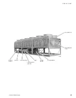
GENERAL DESCRIPTION
The Air Cooled Screw Chiller utilizes many components
which are the same or nearly the same as a standard
reciprocating chiller of a similar size. This includes
modular frame rails, condenser, fans and evaporator.
The chiller consists of two screw compressors in two
separate refrigerant circuits, a single shell and tube DX
evaporator, economizers, an air cooled condenser, and
expansion valves. Standard efficiency chillers have 4
fans per refrigerant system and operate in pairs. High
efficiency chillers have 6 fans per refrigerant system and
operate in groups of 3 (trio).
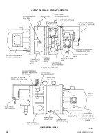
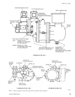
COMPRESSOR
The Frick semi-hermetic rotary twin-screw compressor
utilizes a twin screw design with a single slide valve for
capacity control. The compressor is a positive
displacement type characterized by two helically grooved
rotors. The 60 Hz motor operating at 3570 RPM drives a
geared speed increaser to drive the male rotor between
4125 - 7600 RPM. The female rotor is driven by the male
rotor on a light film of oil. Compressors with gear sets
running at higher speeds will have greater capacity.
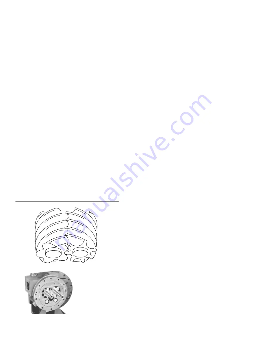
Refrigerant gas is injected into the void created by the un-
meshing of the 5 lobed male and 7 lobed female rotor.
Further meshing of the rotors closes the rotor threads to
the suction port and progressively compresses the gas in
an axial direction toward the discharge port. The gas is
compressed in volume and increased in pressure before
exiting at a designed volume at the discharge end of the
rotor casing. Since the intake and discharge cycles
overlap, a resulting smooth continuous flow of gas is
maintained.
Contact between the male and female rotor is primarily
rolling on a contact band on each of the rotors pitch circle.
This results in virtually no rotor wear and increased
reliability, a trademark of the screw compressor.
The compressor incorporates a complete anti-friction
bearing design for reduced power input and increased
reliability. Four separated, cylindrical, roller bearings
handle radial loads. Angular-contact ball bearings handle
axial loads. Together they maintain accurate rotor
positioning at all pressure ratios, thereby minimizing
leakage and maintaining efficiency. A check valve is
installed in the compressor discharge housing to prevent
compressor rotor backspin due to system refrigerant
pressure gradients during shutdown.
Motor cooling is accomplished by injecting intermediate
pressure wet vapor into the motor which allows for better
efficiency than the traditional use of lower pressure
suction gas which requires more energy to raise to
discharge pressure. On demand high pressure liquid
injection provides additional motor cooling when internal
oil temperatures ruse. Addtional motor cooling required
during low load operation is supplied by a 5 ton TXV. A
drain line drains excess liquid from the motor housing and
feeds it into the gear cavity.
The compressor is lubricated by removing oil from the
refrigerant using an external oil separator. The pressur-
ized oil is then piped back to the compressor for
lubrication. The compressor design working pressure is
144 PSIG on the discharge side. Each chiller receives a
300 PSIG low side and 450 PSIG high side factory test.
A 500 watt (115-1-60) immersion heater is located in the
compressor. The heater is temperature activated to
prevent refrigerant condensation.
EVAPORATOR
The system uses a Shell and Tube type Direct Expansion
Evaporator. Each of the two refrigerant circuits consists
of 4 passes with the chilled liquid circulating back and
forth across the tubes from one end to the other. The
design working pressure of the cooler shell on the liquid
side is 150 PSIG, and 235 PSIG for the tube (refrigerant
side). The cooler is equipped with a heater to provide
freeze protection to -20°F (-28.8°C).
Water connections are grooved to accept victaulic
couplings.
FIG. 4 – COMPRESSOR ROTORS
LD01095
ACTUAL
ROTOR
ASSEMBLY
27936A(D)
Содержание Millennium YCAS 216X
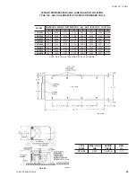
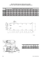
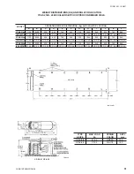
Страница 11: ...FORM 201 10 NM1 11 YORK INTERNATIONAL YCAS 140 246 DIMENSIONS English LD01444 LD01446...
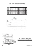
Страница 13: ...FORM 201 10 NM1 13 YORK INTERNATIONAL YCAS 140 246 DIMENSIONS SI LD01440 LD01442...
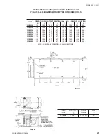
Страница 15: ...FORM 201 10 NM1 15 YORK INTERNATIONAL YCAS 216X 266X DIMENSIONS English LD01454 LD01454...
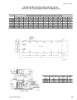
Страница 17: ...FORM 201 10 NM1 17 YORK INTERNATIONAL YCAS 216X 266X DIMENSIONS SI LD01450 LD01448...
Страница 33: ...FORM 201 10 NM1 33 YORK INTERNATIONAL 28514A FILTER DRYER LIQUID STOP VALVE...
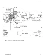
Страница 37: ...FORM 201 10 NM1 37 YORK INTERNATIONAL LD01285 FIG 3 SCREW CHILLER REFIGERANT FLOW DIAGRAM...
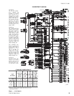
Страница 54: ...54 YORK INTERNATIONAL FIG 9 SYSTEM WIRING YCAS 140 246 CONNECTION DIAGRAM SYSTEM WIRING LD01466 D...
Страница 59: ...FORM 201 10 NM1 59 YORK INTERNATIONAL FIG 11 CONTINUED LD01465 D...
Страница 60: ...60 YORK INTERNATIONAL FIG 12 CONNECTION DIAGRAM WYE DELTA YCAS 140 246 CONNECTION DIAGRAM WYE DELTA LD01458 D...
Страница 61: ...FORM 201 10 NM1 61 YORK INTERNATIONAL FIG 12 CONTINUED LD01458 D...
Страница 69: ...FORM 201 10 NM1 69 YORK INTERNATIONAL FIG 16 CONTINUED LD01206 D...
Страница 71: ...FORM 201 10 NM1 71 YORK INTERNATIONAL FIG 17 CONTINUED LD01202 D...


