112
YORK INTERNATIONAL
ANTICIPATION SAFETY CONTROLS
Anticipation controls are built into the software to pre-
vent safety shutdowns by automatically overriding tem-
perature controls, if system conditions approach safety
thresholds. This allows the chiller capacity to avoid total
loss of cooling resulting from a lockout on a safety.
Anticipation safeties monitor suction and discharge pres-
sure and unload the compressor’s as needed. The micro
will display a message on the STATUS DISPLAY when-
ever these controls are in operation.
Discharge Pressure Unloading
The purpose of this safety is to reduce the chance of
faulting on the internal or external high discharge pres-
sure cut-out which will cause total cooling loss in the
system. The micro will unload the system in an effort to
keep the discharge pressure below the cut-out.
For the first 60 seconds of operation, the unloading safety
is ignored. After 60 seconds, if discharge pressure ex-
ceeds the Discharge Pressure Unload setpoint pro-
grammed by the user (Page 90), the micro will unload the
affected compressor by sending a one second unload
pulse to the slide valve. Continued unloading will occur
every 5 seconds until the discharge pressure drops be-
low the programmed setpoint.
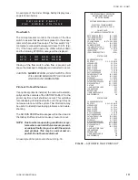
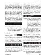
The micro will automatically extinguish the Status dis-
play DSCH LIMITING and reload the compressor, if de-
mand requires, when the discharge pressure drops be-
low 90% of the programmed setpoint.
The operation of this safety becomes important if con-
denser coils become dirty, a problem exists with con-
denser fan operation, or if extreme ambient or load con-
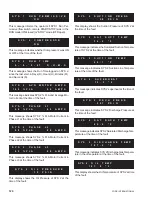
ditions occur. A STATUS message will be displayed when-
ever discharge pressure unloading is in effect. An ex-
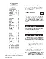
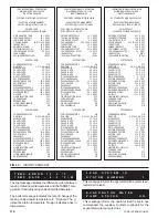
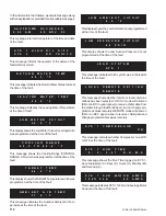
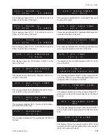
ample of this message is shown below:
Motor Current Unloading
The purpose of this safety is to reduce the chance of
faulting due to high motor current causing total loss of
cooling in the system. The micro will unload the system
in an effort to keep the motor current from exceeding the
high motor Current Cut-out.
For the first 60 seconds of operation, the unloading safety
is ignored. After 60 seconds of operation, if motor cur-
rent exceeds the Current Limit Setpoint programmed by
the user (Page 90), the micro will unload the affected
compressor by sending a one second unload pulse to
the slide valve. Continued unloading will occur every 5
seconds until the motor current drops below the pro-
grammed setpoint.
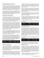
The micro will automatically extinguish the CURR LIMIT-
ING Status display and reload the compressor if demand
requires and the motor current drops below 90% of the
programmed cut-out.
The operation of this safety also becomes important when
demand limiting is critical due to power requirements or
limitations in the building.
In some cases current limiting may come into play if
abnormally high outdoor temperatures are encountered
and high discharge pressures cause motor currents to
rise near the safety cut-out point.
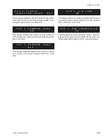
An example of the Current Limiting display message is
shown below:
Suction Temp Limiting
SUCTION LIMITING is only operable when optional elec-
tronic expansion valves are added to the chiller. If suc-
tion pressure exceeds the programmed pressure, the
micro will allow superheat to rise above the setpoint in
an attempt to reduce suction pressures. This is done to
assure that adequate motor cooling is provided. Normally,
the default value is sufficient and programming is not
necessary. Details on programming this feature are out-
lined on page 90.
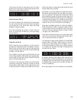
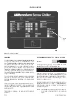
An example of the SUCT LIMITING display message is
shown below:
INTERNAL TIMERS AND PUMPDOWN CONTROLS
Anti-Recycle Timer
Anytime a compressor shuts down for any reason, re-
start cannot occur until the programmable Anti-recycle
Timer (Page 91) has timed out (timer starts with the com-
pressor start). Even though the Anti-recycle timer has
timed out, a minimum of 2 minutes (2 - minute start-up
timer) must always elapse after a compressor shuts down,
before it may again restart.
If a power failure occurs, the anti-recycle timers will re-
set to 2 minutes after power is re-applied.
S Y S
1
D S C H
L I M I T I N G
S Y S
2
D S C H
L I M I T I N G
S Y S
1
S U C T
L I M I T I N G
S Y S
2
S U C T
L I M I T I N G
S Y S
1
C U R R
L I M I T I N G
S Y S
2
C U R R
L I M I T I N G
Содержание Millennium YCAS 216X
Страница 11: ...FORM 201 10 NM1 11 YORK INTERNATIONAL YCAS 140 246 DIMENSIONS English LD01444 LD01446...
Страница 13: ...FORM 201 10 NM1 13 YORK INTERNATIONAL YCAS 140 246 DIMENSIONS SI LD01440 LD01442...
Страница 15: ...FORM 201 10 NM1 15 YORK INTERNATIONAL YCAS 216X 266X DIMENSIONS English LD01454 LD01454...
Страница 17: ...FORM 201 10 NM1 17 YORK INTERNATIONAL YCAS 216X 266X DIMENSIONS SI LD01450 LD01448...
Страница 33: ...FORM 201 10 NM1 33 YORK INTERNATIONAL 28514A FILTER DRYER LIQUID STOP VALVE...
Страница 37: ...FORM 201 10 NM1 37 YORK INTERNATIONAL LD01285 FIG 3 SCREW CHILLER REFIGERANT FLOW DIAGRAM...
Страница 54: ...54 YORK INTERNATIONAL FIG 9 SYSTEM WIRING YCAS 140 246 CONNECTION DIAGRAM SYSTEM WIRING LD01466 D...
Страница 59: ...FORM 201 10 NM1 59 YORK INTERNATIONAL FIG 11 CONTINUED LD01465 D...
Страница 60: ...60 YORK INTERNATIONAL FIG 12 CONNECTION DIAGRAM WYE DELTA YCAS 140 246 CONNECTION DIAGRAM WYE DELTA LD01458 D...
Страница 61: ...FORM 201 10 NM1 61 YORK INTERNATIONAL FIG 12 CONTINUED LD01458 D...
Страница 69: ...FORM 201 10 NM1 69 YORK INTERNATIONAL FIG 16 CONTINUED LD01206 D...
Страница 71: ...FORM 201 10 NM1 71 YORK INTERNATIONAL FIG 17 CONTINUED LD01202 D...

