


40
YORK INTERNATIONAL
valve open to load the compressor. Electrical pulses open
a solenoid valve, allowing oil pressure to move the piston
which operates the slide valve. The pulses originate at the
micro and are a function of the required load on the chiller
in response to leaving water temperature.
The micro must repetitively pulse the slide valve to
maintain a constant load. This is required because
discharge pressure is always present on the other end of
the slide valve, trying to force it closed.
To unload the compressor, a second solenoid is opened,
which vents oil pressure away from the piston. By
releasing the pressure on the piston, the discharge
pressure is able to push the valve toward the closed or
unload position.
It will be noted that slide valve movement is greater at high
discharge pressures. This is due to higher oil pressure
which is directly proportional to discharge pressure.
Higher oil pressures exert more pressure on the slide
valve causing greater movement as the slide valve is
pulsed with oil. This condition is normal. Also normal and
a result of compressor design is non-linear movement at
various points in the slide valve travel as the slide valve
is pulsed. Closely monitoring the movement will show that
the slide valve will move easier at the ends and in the
center of its travel range.
When the compressor is shut down, a check valve
releases oil from the piston. Since no discharge pressure
is available to push the valve closed, the slide valve will
maintain the position it was in when the compressor
stopped. To assure the compressor starts unloaded, the
micro sends an unload signal to the slide valve on start-
up. In some cases, oil pressure may not be high enough
at start-up to move the slide valve. This means the
compressor could start-up partially loaded. This will
seldom occur and will not hurt the motor due to the extra
torque built into the design.
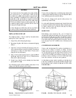
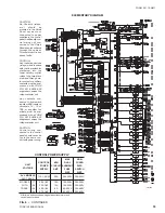
STARTER
Two types of compressor motor starting are available:
Across-the-line and optional Wye-Delta Closed Transition
Starter. The Across-the-line starters will utilize one
contactor per compressor.
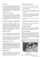
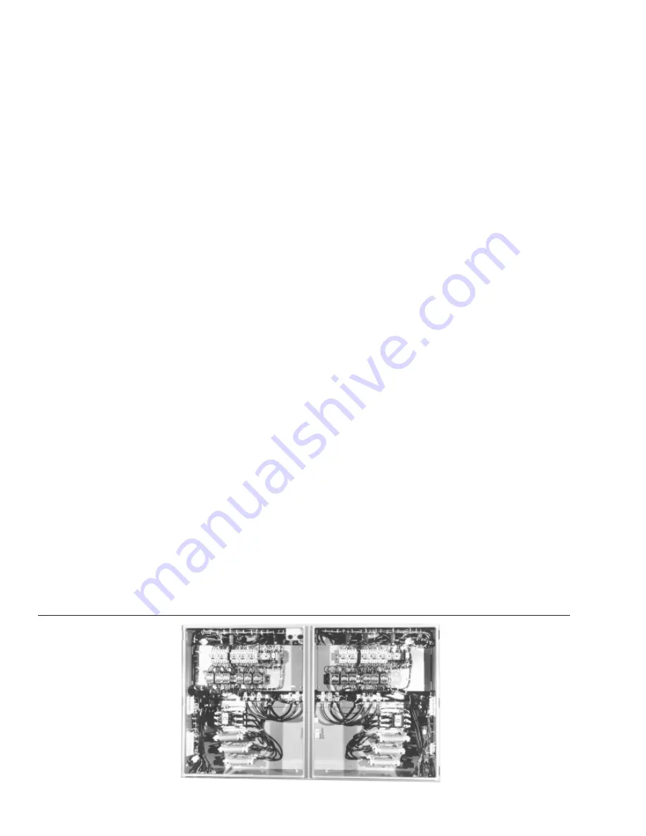
The optional Wye-Delta starter utilizes 4 contactors, a
time delay relay, and wire wound power resistors for each
compressor. See Fig. 5.
The Wye-Delta start allows inrush current to be limited to
approximately 33% LRA for the first 15 seconds with
current increasing to normal running current when the
Delta connection is completed.
When the micro initiates a start signal to run a
compressor, the 1CR (SYS 1) or 2CR (SYS 2) relay is
energized. At the same time, the 1TR (SYS 1) or 2TR
(SYS 2) “15 second” time delay relay is energized and
begins timing. The transition of the 1CR (SYS 1) or 2CR
(SYS 2) contactor also energizes 1S (SYS 1) or 2S (SYS
2) normally open auxiliary interlock contacts after
approximately 16ms which in turn energizes the 1M (SYS
1) or 3M (SYS 2) motor contactor after approximately
another 16ms. This completes the “WYE” connection of
the motor start. At the same time, the normally closed 1S
or 2S auxiliary interlock open, preventing 2M (SYS 1) or
4M (SYS 2) from energizing.
The “WYE” connection of the motor start is enabled for
approximately 15 seconds. When the 1TR or 2TR timer
times out after 15 seconds, the interlock contacts
energize 1A (SYS 1) or 2A (SYS 2) “TRANSITION”
contactor which puts the resistance networks across
each winding of the “WYE” connection. At the same time,
the normally closed 1A or 2A auxiliary interlock contacts
de-energize 1S or 2S after approximately 16ms. The
normally closed auxiliary interlock contacts on 1S or 2S
will close energizing 2M or 4M after approximately 16ms.
With the 1M or 3M contactors already held in by the 1M
or 3M auxiliary contacts and 2M or 4M energized, the
normally closed auxiliary interlock contact on 2M or 4M
contactor holding in the 1A or 2A “TRANSITION” contactor
opens removing the resistor network and completing the
“DELTA” connection of the “WYE-DELTA” start.
FIG. 5 – POWER PANEL (WITH WYE-DELTA STARTING)
27963A
Содержание Millennium YCAS 216X
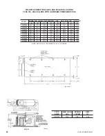
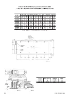
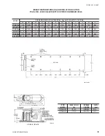
Страница 11: ...FORM 201 10 NM1 11 YORK INTERNATIONAL YCAS 140 246 DIMENSIONS English LD01444 LD01446...
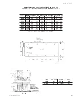
Страница 13: ...FORM 201 10 NM1 13 YORK INTERNATIONAL YCAS 140 246 DIMENSIONS SI LD01440 LD01442...
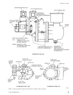
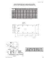
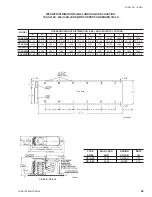
Страница 15: ...FORM 201 10 NM1 15 YORK INTERNATIONAL YCAS 216X 266X DIMENSIONS English LD01454 LD01454...
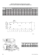
Страница 17: ...FORM 201 10 NM1 17 YORK INTERNATIONAL YCAS 216X 266X DIMENSIONS SI LD01450 LD01448...
Страница 33: ...FORM 201 10 NM1 33 YORK INTERNATIONAL 28514A FILTER DRYER LIQUID STOP VALVE...
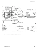
Страница 37: ...FORM 201 10 NM1 37 YORK INTERNATIONAL LD01285 FIG 3 SCREW CHILLER REFIGERANT FLOW DIAGRAM...
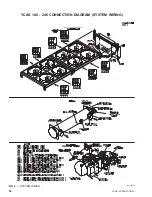
Страница 54: ...54 YORK INTERNATIONAL FIG 9 SYSTEM WIRING YCAS 140 246 CONNECTION DIAGRAM SYSTEM WIRING LD01466 D...
Страница 59: ...FORM 201 10 NM1 59 YORK INTERNATIONAL FIG 11 CONTINUED LD01465 D...
Страница 60: ...60 YORK INTERNATIONAL FIG 12 CONNECTION DIAGRAM WYE DELTA YCAS 140 246 CONNECTION DIAGRAM WYE DELTA LD01458 D...
Страница 61: ...FORM 201 10 NM1 61 YORK INTERNATIONAL FIG 12 CONTINUED LD01458 D...
Страница 69: ...FORM 201 10 NM1 69 YORK INTERNATIONAL FIG 16 CONTINUED LD01206 D...
Страница 71: ...FORM 201 10 NM1 71 YORK INTERNATIONAL FIG 17 CONTINUED LD01202 D...


