


106
YORK INTERNATIONAL
SAFETIES
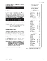
GENERAL
There are both System Safeties and Total Chiller Safe-
ties programmed into the micropanel. System Safeties
may either be Manual Reset or Anticipation Type. Chiller
safeties will be Automatic Reset Type. These safeties
protect the chiller from damage anytime a safety thresh-
old is exceeded by either shutting the system(s) down or
by altering system loading. Continuous monitoring by the
microprocessor assures that instantaneous reactions
result. A status display message will indicate when a
system(s) or the entire chiller is shut down due to a fault
or when Anticipation safeties are operating.
An explanation of these safeties follows.
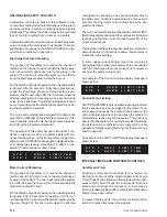
MANUAL RESET SAFETIES
A Manual Reset Safety will shut the affected system
down whenever the safety threshold is exceeded. Auto-
matic restart will occur after the first 2 shutdowns when
the anti-recycle timer times out, if temperature demand
exists. After any combination of 3 Manual Reset Safe-
ties in a 90 minute time period, the affected system will
shut down and lock out on a FAULT.
After a system has shut down 3 times and locked out, a
fault display indicating the last system fault will appear
on the STATUS display message. This is accessible by
pressing the STATUS key.
NOTE: The High Motor Current Safety is a unique safety
that will lock out a system after only a single
fault.
To reset a locked out system, turn the affected system
switch on the Microprocessor Board (Page 125) to the
OFF position.
CAUTION: Before returning a locked out system to ser-
vice, a thorough investigation of the cause
of the fault should be made. Failure to repair
the cause of the fault while manually allow-
ing repetitive restarts may cause further ex-
pensive damage to the system.
Each of the Manual Reset Safeties will be discussed in
detail below.
Discharge Pressure Safety
The Discharge Pressure Safety assures that the system
pressure does not exceed safe working limits which could
open a relief valve or other pressure relief device caus-
ing refrigerant loss.
This safety is a back-up for the mechanical High Pres-
sure Cut-out in the system. The Discharge Pressure
Safety is bypassed for the first 5 seconds of operation.
After 5 seconds, if the cut-out point is exceeded for 3
seconds, the system will shut down.
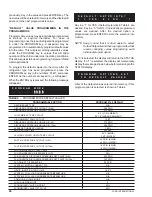
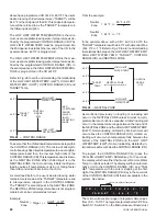
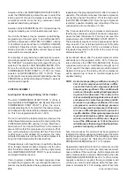
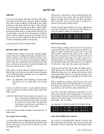
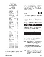
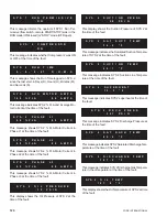
The Discharge Pressure Safety Cut-out is programmable
by the user (Page 89). An example of a discharge pres-
sure fault display message is shown below:
Oil Pressure Safety
The Oil Pressure Safety assures that the compressor’s
mechanical components receive proper lubrication. This
safety monitors the pressure drop across the oil filter
and isolation valves that are present in the oil line be-
tween the oil separator and the compressor. The micro
begins monitoring compressor oil pressure after 3 min-
utes of operation. If oil pressure increases above (pres-
sure drops) the differential oil pressure cut-out threshold
for more than 3 seconds, the system will shut down.
Under typical operation, the oil pressure display will nor-
mally read less than 45 PSID. As oil pressure drops, the
differential pressure on the display will increase, which
means that oil pressure is moving closer to suction pres-
sure. Optimum oil pressure will approach 0 PSID on the
micropanel display.
After 3 minutes of operation, oil pressure must be less
than 45 PSID (R22) or 40 PSID (R134a) for as long as
the compressor continues to run. If the required oil pres-
sure limits are not met, the system will shut down.
The micro computes “differential oil pressure” for this
safety by measuring discharge pressure as sensed by
the discharge transducer and subtracting oil pressure as
sensed by the oil transducer returning to the compressor
(Discharge - Oil = Oil PSID).
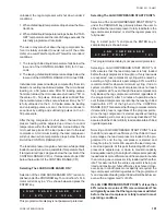
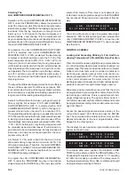
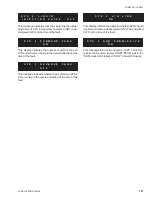
An example of a high oil pressure fault display follows:
LOW OIL DIFFERENTIAL SAFETY
The LOW OIL DIFFERENTIAL SAFETY assures that
the compressor’s mechanical components receive proper
lubrication. This is accomplished by monitoring the pres-
S Y S
1
H I G H
D S C H
P R E S
S Y S
2
H I G H
D S C H
P R E S
S Y S
1
H I G H
O I L
D I F F
S Y S
2
H I G H
O I L
D I F F
Содержание Millennium YCAS 216X
Страница 11: ...FORM 201 10 NM1 11 YORK INTERNATIONAL YCAS 140 246 DIMENSIONS English LD01444 LD01446...
Страница 13: ...FORM 201 10 NM1 13 YORK INTERNATIONAL YCAS 140 246 DIMENSIONS SI LD01440 LD01442...
Страница 15: ...FORM 201 10 NM1 15 YORK INTERNATIONAL YCAS 216X 266X DIMENSIONS English LD01454 LD01454...
Страница 17: ...FORM 201 10 NM1 17 YORK INTERNATIONAL YCAS 216X 266X DIMENSIONS SI LD01450 LD01448...
Страница 33: ...FORM 201 10 NM1 33 YORK INTERNATIONAL 28514A FILTER DRYER LIQUID STOP VALVE...
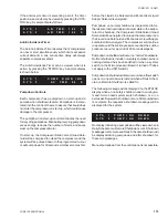
Страница 37: ...FORM 201 10 NM1 37 YORK INTERNATIONAL LD01285 FIG 3 SCREW CHILLER REFIGERANT FLOW DIAGRAM...
Страница 54: ...54 YORK INTERNATIONAL FIG 9 SYSTEM WIRING YCAS 140 246 CONNECTION DIAGRAM SYSTEM WIRING LD01466 D...
Страница 59: ...FORM 201 10 NM1 59 YORK INTERNATIONAL FIG 11 CONTINUED LD01465 D...
Страница 60: ...60 YORK INTERNATIONAL FIG 12 CONNECTION DIAGRAM WYE DELTA YCAS 140 246 CONNECTION DIAGRAM WYE DELTA LD01458 D...
Страница 61: ...FORM 201 10 NM1 61 YORK INTERNATIONAL FIG 12 CONTINUED LD01458 D...
Страница 69: ...FORM 201 10 NM1 69 YORK INTERNATIONAL FIG 16 CONTINUED LD01206 D...
Страница 71: ...FORM 201 10 NM1 71 YORK INTERNATIONAL FIG 17 CONTINUED LD01202 D...


