


2-20
IM WT5000-02EN
2.6 Setting the Sensor Correction
► “Sensor Correction (Sensor Correction)” in the features guide
This section explains operating procedures using the following setup methods.
• Procedure Using the Setup Menu (see chapter 1)
• Procedure Using the Menu Icons (see page xiv)
Procedure Using the Setup Menu
1.
Tap the
Setup
icon
, or press
MENU
under SETUP.
2.
Tap
the Input (Advanced/Options)
tab. An input settings (advanced/options) overview screen
appears.
Pressing
ESC
closes the overview screen.
3.
Tap
Sensor Correction
. A sensor correction setup screen appears.
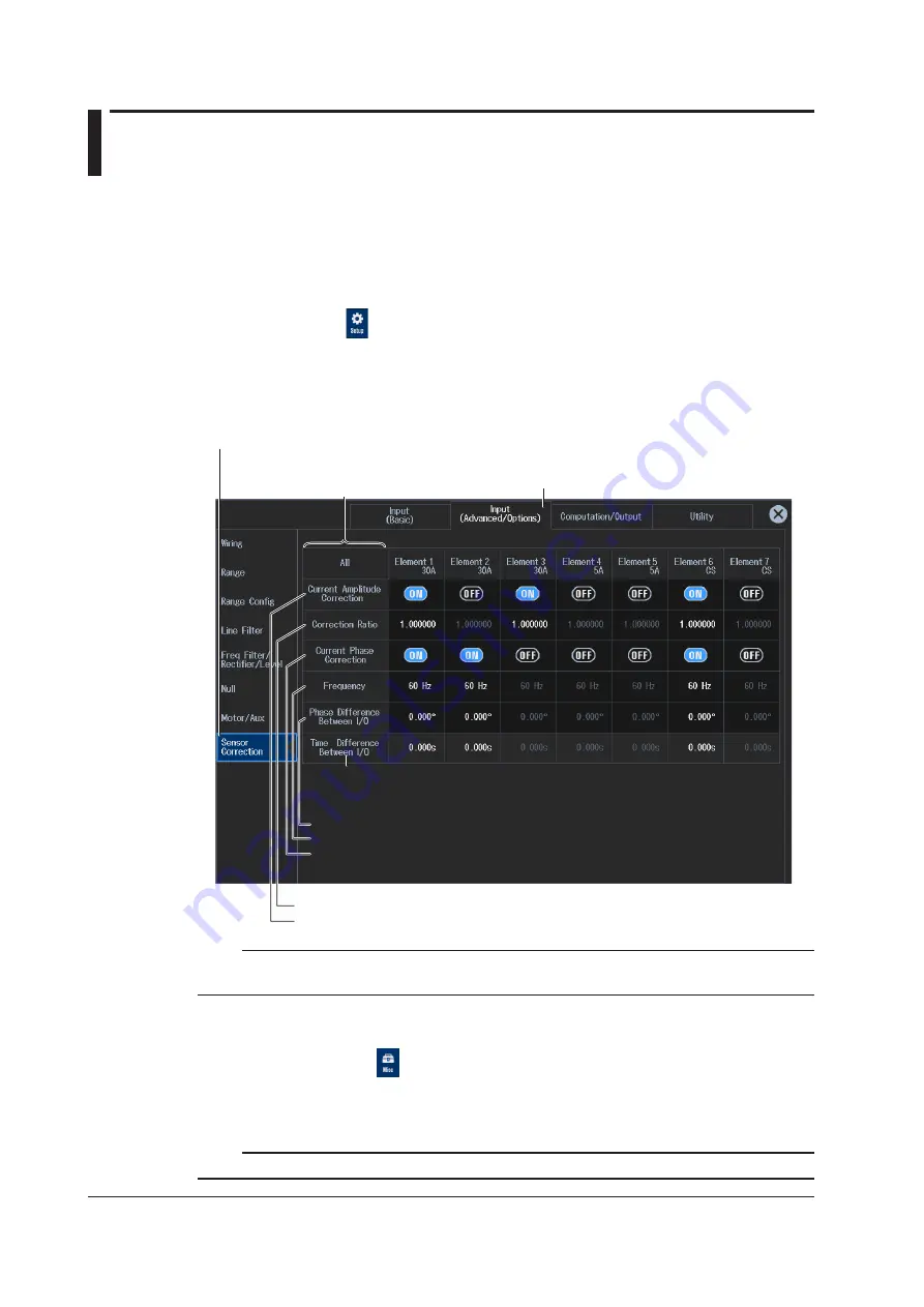
Input (Advanced/Options) tab
Sensor Correction button
By tapping the item names in the left edge, you can
collectively set all input elements (except the Time
Difference between I/O item at the bottom).
Time difference between input and output
Current phase correction
• Set the phase error between input and output (–180.000° to +180.000°).
• Set frequency (50 Hz, 60 Hz, 0.1 kHz to 999.9 kHz, 1 MHz).
• Turns the phase correction on and off
Current amplitude correction
• Set the correction ratio (0.800000 to 1.200000).
• Turns current amplitude correction on and off
Note
You can also display the input settings (advanced/options) overview screen by moving the cursor on the
Input (Advanced/Options) tab using the arrow keys and then pressing SET.
Procedure Using the Menu Icons
You can also use the menu icons shown on the right side of the screen to set the sensor correction.
1.
Tap the
Misc
menu icon
. A Misc menu appears in the sub menu area on the right side of
the screen.
By tapping the displayed items, you can specify the same settings as when using the screen explained
earlier.
Note
For details on the Misc menu, see page xiv.


