40
PRINCIPLE OF OPERATION
The quadrature decoder board generates up (+) and down (-) counts that are arithmetically
totalized on the main counter board and are then displayed. The decoder board has input
circuitry that may be jumpered for single-ended input signals or balanced line driver signals.
It accepts normal A & B quadrature signals and, if present, a zero index signal. The A & B
signals are 90º out of phase, and their phase relationship determine whether Up counts are
added to the total, or Down counts are subtracted from the total.
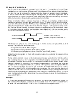
Since incremental optical encoders may have a different A & B phase relationship to
indicate up and down counting, the board has a jumper E7 (BPOL) on the B signal to allow
selection of the desired phase. With the jumper not installed, Up output pulses are created
when the B signal has a positive transition while the A signal is at a positive level (A leads
B). With the jumper installed, Up output pulses are created when the B signal has a nega-
tive transition while the A signal is at a positive level (B leads A). With the opposite phase
shown, the effect of E7 reverses.
A Channel
B Channel
With E7 open, counts up.
With E7 jumpered, counts down .
The board has jumpers that allow counting by 1, 2 or 4 counts per cycle of the A or B
signals. The edges that are counted are:
X1 = positive transitions of the A signal.
X2 = positive and negative transitions of the A signal.
X4 = positive and negative transitions of both the A and the B signals.
Digital filtering is provided for the A & B signals to reduce the probability of noise providing
false counts.
Some optical encoders create a zero index signal once per revolution that indicates when
the encoding wheel is at its zero position. Each time this signal is created, the total count
should be a multiple of the number of counts per revolution of the coding wheel. If this
feature is enabled in the counter, the counter checks to see if total counts are an exact
multiple of the counts per revolution. If so, it does nothing, and if not, it changes the total to
the closest exact multiple. The counts per revolution are entered into the counter via the
menu item Pulses. From 0 to 59,999 pulses may be entered. If X2 or X4 counting is enabled
on the board, the value entered into Pulses should be the counts (or pulses) per revolution
of the encoder multiplied by this factor of X2 or X4. If Scale is a factor other than 1, include it
as a multiplying factor when determining the value of Pulses to enter. Do not include the
value of OFFSET1.
Example:
If the encoder produces 256 cycles per revolution, X2 counting is selected by a jumper on
the board and from the front panel Menu of the counter, SCALE1 is set to 3, and OFFSET1
is set to 100, then set PULSES = 256 x 2 x 3 = 1536 from the front panel menu.
Содержание 800 plus
Страница 63: ...63 SERIAL CONNECTION EXAMPLES ...


