43
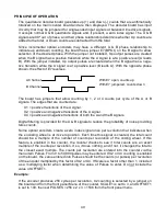
By ANDing the zero index signal with the A & B channels, there is no regional discrepancy
between counting up and counting down.
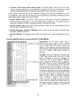
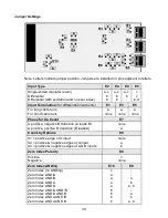
There are 2 control signals, C1 and C2, and 3 outputs, ZI, ZIX and ZIY. These may be
jumpered to provide 8 selections of ANDed signals or the zero index signal without ANDing.
Zero Index Polarity
Jumper Position
E8
Positive
Negative
None
c
Zero Index ANDing
Jumper Position
E10
E8
Zero Index (no ANDing)
Zero Index AND /A
Zero Index AND /B
Zero Index AND A
Zero Index AND B
Zero Index AND /A AND /B
Zero Index AND /A AND B
Zero Index AND A AND /B
Zero Index AND A AND B
C
a
a
a
a
b
b
b
b
-
-
a
b
a, b
-
a
b
a, b
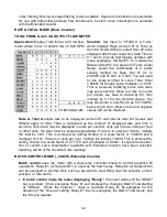
The manufacture's data sheet for the optical encoder will show the position and width of the
zero index signal with respect to the A channel and B channel signals. Selection of one of
the above combinations depends on that relationship and the polarity of the channel A & B
signals when the mechanical position is zero. Be sure to take into account the selected
phase relationship determined by the presence of or absence of jumper E7-a (BPOL).
Jumper E7-a is selected to cause the display to count in the proper direction. If jumper E7 is
in place, the channel B signal will have the opposite polarity from the channel B output of
the encoder.
MECHANICAL ZERO
By using the Counter’s OFFSET1 value, it is possible to place the mechanical
zero (zero counter reading) at some point other than the location of the zero
index. The following technique describes how to accomplish this.
1.
Set the E8 & E10 jumpers as described above to produce the desired Zero Index signal.
2.
Set OFFSET1 = 0.
3.
Reset the counter (counter reset).
4.
Rotate the optical encoder in the positive direction until the reading jumps to zero at the
zero index point (Item indicator lights).
5.
Reverse the direction of rotation until the desired zero mechanical position is reached.
6.
Note the reading and enter that reading into OFFSET1 using the opposite polarity of the
display.
7.
Reset the counter, and it will display the OFFSET1 value because the internal total
counter = 0 and the correction = 0. The position of the encoder when the counter is
reset is not critical.
Содержание 800 plus
Страница 63: ...63 SERIAL CONNECTION EXAMPLES ...


