32
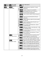
noise filtering. Moving average filtering is also available. Square root extraction is selectable
for use with differential pressure flow transducers. Custom curve linearization is available
with the Extended counter.
RATE & TOTAL MODE (Basic Counter)
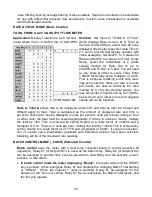
TOTAL FROM A 4-20 mA OUTPUT FLOW METER
Application:
Display Total from a 4-20 mA flow
meter where 4 mA = 0 and 20 mA = 5.820 GPM.
Solution:
Set Input to “VF420 A A Total,”
which displays Rate as Item #1 & Total as
Item #2. Under dSPyno, select Item #2 to be
displayed after meter reset. Set Gate Time to
0.1 sec to provide fast display updates with
noise averaging. Set DecPt1 to 3 places for
Rate and DecPt2 to 2 places for Total. Under
Setup, select the coordinates of 2 points
scaling method for Rate. Set Hi In1 to
20.0000 and Hi Rd1 to 5.820. You will need
to use scale & offset to scale Total. Enter
1.66667 for Scale2 and a multiplier of 0.001.
That is because totalizing sums rate read-
ings every second. Since our rate is in units
per minute, we have to divide by 60, then
multiply by 0.1 for two decimal places. You
may also enter a Cutoff such as 0.010 GPM,
below which zero offset errors and negative
values will not be totalized.
Rate A, Total A
allows rate to be displayed as Item #1 and total as Item #2. Scale2 and
Offset2 apply to total. Total is calculated as the product of displayed rate and time in
seconds. Since rate may be displayed in units per second, units per minute, units per hour
or other units, the total must be scaled appropriately. If rate is in units per minute, multiply
the total by 1/60. This is achieved by setting Scale2 to a scale factor of 1.66666 and a
multiplier of 0.01. If rate is in units per hour, multiply the total by 1/3600. This is achieved by
setting Scale2 to a scale factor of 2.77778 and a multiplier of 0.0001. If square root extrac-
tion or custom curve linearization (available with Extended counter) have been selected,
totalizing will be of the linearized rate readings.
BATCH CONTROL MODE (
_
bAtCH) (Extended Counter)
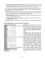
Batch control
uses the meter with a dual relay controller board to control repetitive fill
operations. Relay #1 (or Setpoint #1) is used as the batch relay. Relay #2 (or Setpoint #2)
can be assigned to another limit, such as pre-warn to slow filling near the setpoint, end-of-
process, or rate alarm.
•
In batch control mode the meter displaying “Ready”,
the meter waits until the
RESET
key is pushed, it then energizes Relay #1 and displays the changing Batch Total starting
at “Offset2”. When the setpoint 1 value is reached, Relay #1 de-energizes for the
duration of the “time out” setting. Relay #1 then re-energizes, the Batch Total resets, and
the fill cycle repeats.
Содержание 800 plus
Страница 63: ...63 SERIAL CONNECTION EXAMPLES ...


