31
11. PROCESS RECEIVER & TOTALIZER SIGNAL CONDITIONER
This signal conditioner board converts 0-1 mA, 4-20 mA or 0-10 V analog process signals to
a frequency signal, which is then read by the counter main board and processed
mathematically for display of rate, total (time x rate), time based on rate, or batch control.
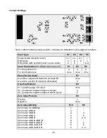
The board needs to be configured via jumpers for the input signal range. The meter
software recognizes the board and brings up the applicable menu items for it.
Please see further manual pages for the following features: relay output, analog output,
serial communications, and transducer excitation output.
JUMPER SETTINGS
Input Range
Jumper Position A1
0-10V
0-1 mA
4-20 mA
None
a
b
OPERATING MODES
RATE FROM A 4-20 mA OUTPUT FLOW METER
Application:
Display rate in GPM to 3 deci-
mal places from a 4-20 mA flow meter where
4 mA = 0 GPM and 20 mA = 5.820 GPM.
Solution:
Set Input to “VF420 A only.” Un-
der Setup, select the coordinates of 2 points
scaling method. Under Config, select a dis-
play of 999999 and filtering. Set the decimal
point to 3 places. For scaling, set Hi In1 to
20.0000 and Hi Rd1 to 5.820. Set Gate Time
to 0.22 sec, which will provide noise aver-
aging at a display update rate of 4/sec. Also
set a 1.6 sec adaptive moving average filter
to process the equivalent of 6 readings.
RATE MODE (Basic Counter)
Rate A
accepts 0-1 mA, 4-20 mA or 0-10 V analog process signals for a process display
scaled to engineering units. Scaling is normally done using the coordinates of 2 points
method, where low and high input signals and the corresponding desired low and high
displayed values are entered. Scaling can also be done by entering scale and offset directly.
With Scale1 set to 1 and Offset1 set to 0, the full analog input range is displayed as 0-
100000. Measurements are averaged over a gate time, which is programmable from 10 ms
to 199.99 sec. Selecting a long gate time provides a slower display update rate but superior
Содержание 800 plus
Страница 63: ...63 SERIAL CONNECTION EXAMPLES ...


