21
•
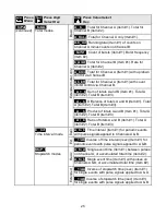
INVERSE STOPWATCH TIME A TO A & A TO B (
__
1/AA & 1/AB)
(Extended counter)
Takes the inverse of stopwatch time for a reading in /second. For example, if the travel
time for an object to travel from point A to point B is 5 seconds, the inverse stopwatch
time interval would be 0.2/sec. For the speed of that object, simply multiply by a scale
factor equal to the distance separating the two points, such as 7 (inches). Speed would
then be displayed as 7 x 0.2 = 1.4 (inches/sec). For a 6-digit reading, apply a scale
multiplier of 10,000 and move the decimal point.
DUTY CYCLE MODE (duty
_
C)
(Extended counter)
Measures ON or OFF period of periodic square waves as a percentage of total period
over a
gate time
which is selectable from 10 ms to 199.99 s. The same signal is applied
to Channels A and B. ON or OFF time is measured between positive and negative edges
of the signal, with averaging over multiple integral periods over the selected gate time.
Apply a scale factor of 1 for readings in percent. Apply a 10 or 100 multiplier and move
the decimal point by 1 or 2 positions for 0.1% or 0.01% resolution.
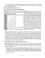
PHASE ANGLE MODE (PHASE)
(Extended counter)
Measures the phase relationship in degrees between two signals with the same period
over a
gate time
which is selectable from 10 ms to 199.99 s, with averaging over multiple
integral periods over the selected gate time. The two signals are applied to Channels A
and B. For best accuracy, both signals should have the same amplitude. The amplitude
of sinusoidal signals should be larger that 1V, and the trigger level should be set at 12
mV (no jumper at A3 or B3, jumper
a
at A2 and B2).
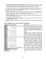
PHASE ANGLE MEASUREMENT TO 0.01º RESOLUTION
Application:
Measure phase angle differ-
ence to 0.01º resolution between two AC
signals centered around 0º.
Solution:
Use an Extended counter, as
required for phase angle measurement.
Jumper the signal conditioner for maximum
sensitivity to catch zero voltage crossings
and minimize the effects of amplitude jitter.
Apply one AC signal to Channel A and one
to Channel B. Set Input to “PHASE +/-
180º.” The display will be in degrees. Set a
gate time of 0.22 sec for 4 display updates
per sec. Set both trigger slopes to positive.
Set two decimal places. Select the coordi-
nates of 2 points scaling method. Set Hi
In1 to 1.00000 (degrees) and Hi Rd1 to
1.00 (degrees). As an alternative, select
the scale and offset scaling method. Then
simply select a scale value of 1.00000 and
a multiplier of 100.
Содержание 800 plus
Страница 63: ...63 SERIAL CONNECTION EXAMPLES ...


