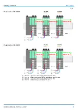


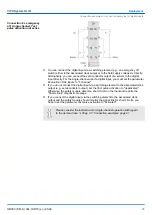


With this connection, you can achieve SIL3/Cat.4/PLe by re-reading the relay states.
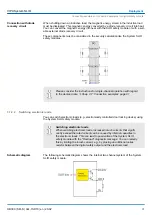
You can connect a load (e.g., a relay) between a digital safety output DO 0 ... 3 and the
ground connection 0V of the field power supply. It is not necessary to lead back the
ground connection to the according connection of the System SLIO safety module.
Please observe the following conditions:
n
Ensure for the fact that the relay and the System SLIO safety module have the same
reference potential.
n
For single fault security, you need at least 2 relays and the cross- circuit fault on the
supply voltage must be excluded by a protected wiring
n
You must connect the normally open contacts (K0 and K1) of 2 relays in series to the
load to be switched.
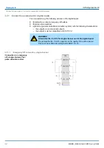
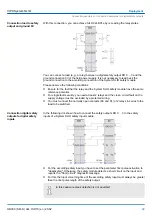
In the following it is shown how to connect the safety outputs DO 0 ... 3 to the safety
inputs of a System SLIO safety input module.
n
For the according safety input you have to set the parameter
Test pulse activation
to
"deactivated". Otherwise, the safety module detects a short circuit on the input and
reports the "Short circuit" diagnostic message.
n
For this the
Input smoothing time
of the according safety input must always be greater
than the
Test pulse length
of the safety output.
In this case wire break detection is not possible!
Connection load to safety
output and ground 0V
Connection digital safety
outputs to digital safety
inputs
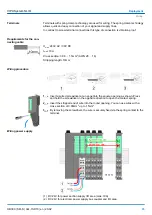
VIPA System SLIO
Deployment
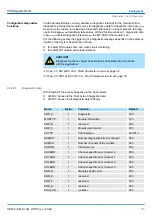
Connection examples > Connection examples for digital safety outputs
HB300 | SM-S | 02x-1SD10 | en | 20-02
99


