


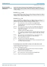


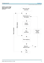


So that the watchdog running in the System SLIO safety modules is regularly reset, that it
does not trigger, the following cyclical data flow should be considered:
T
PSTO
=T
DAT
+ T
ECS
+ T
BUS
+ T
Cl
+ T
BUS
+ T
ECM
+ T
BUS
+ T
Cl
+ T
BUS
+ T
ECS
+ T
DAT
T
PSTO
= 2*T
DAT
+ 2*T
ECS
+ 4*T
BUS
+ 2*T
CI
+ T
ECM
T
PSTO
- Configured safety monitoring time (
FSoE_WD_Time
)
T
DAT
- Max. Acknowledgement time of the System SLIO safety modules (Device
acknowledgement time)
T
ECS
- Max. Response time of the EtherCAT slave, i.e. max. delay due to the EtherCAT
coupler and the backplane bus.
T
BUS
- Time for EtherCAT bus transfer
T
Cl
- Configured cycle time of the safety PLC
T
ECM
- Max. Response time of the EtherCAT slave.
2.10 SDO 4xDC 24V 0.5A - Technical data
Order no.
022-1SD10
Type
SM 022
Module ID
0C82 AE00
Current consumption/power loss
Current consumption from backplane bus
75 mA
Power loss
1 W
Technical data digital outputs
Number of outputs
4
Cable length, shielded
1000 m
Cable length, unshielded
600 m
Rated load voltage
DC 20.4...28.8 V
Current consumption from load voltage L+ (without load)
15 mA
Total current per group, horizontal configuration, 40°C
2 A
Total current per group, horizontal configuration, 60°C
-
Total current per group, vertical configuration
-
Output current at signal "1", rated value
0.5 A
Signal logic output
Sourcing output
Output delay of "0" to "1"
100 µs
Output delay of "1" to "0"
175 µs
Minimum load current
-
Calculating the watchdog
time
VIPA System SLIO
Product description
SDO 4xDC 24V 0.5A - Technical data
HB300 | SM-S | 02x-1SD10 | en | 20-02
55


