


7.2 Specifications and Ratings
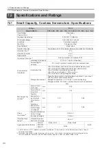
7.2.1 Small-Capacity, Coreless Servomotors: Specifications
7-5
7
Specifications, Ratings, and Exter
nal Dimensions of SGMCS Servomotors
*3.
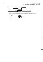
Refer to the following figure for the relevant locations on the Servomotor. Refer to the dimensional drawings of
the individual Servomotors for more information on tolerances.
*4.
The given values are for when the Servomotor shaft is mounted horizontally and shock or vibration is applied in
the directions shown in the following figures.
The strength of the vibration that the Servomotor can withstand depends on the application. Check the vibration
acceleration rate.
A
A
B
B
dia.
dia.
Runout of output shaft surface
Parallelism between mounting surface and output shaft surface
Runout at end of output shaft
Load side
Non-load side
Concentricity between output shaft and flange outer diameter
: Diameter determined by motor model.
Side to side
Front to back
Vertical
Shock Applied to the Servomotor
Vibration Applied to the Servomotor
Vertical