


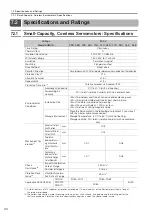

6.2 Specifications and Ratings
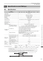
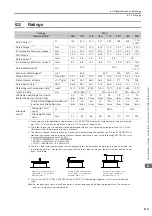
6.2.2 Ratings
6-5
6
Specifications, Ratings, and Exter
nal Dimensions of SGMCV Servomotors
6.2.2
Ratings
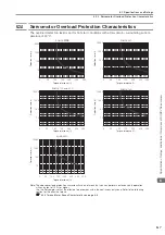
*1.
These values are for operation in combination with a SERVOPACK when the temperature of the armature wind-
ing is 100
°
C. The values for other items are at 20
°
C. These are typical values.
*2.
The rated torques are the continuous allowable torque values at a surrounding air temperature of 40
°
C with a
steel heat sink of the dimensions given in the table.
*3.
To externally connect dynamic brake resistance, select hardware option specification 020 for the SERVOPACK.
However, you cannot externally connect dynamic brake resistance if you use the following SERVOPACKs (max-
imum applicable motor capacity: 400 W).
•
SGD7S-R70
A020 to -2R8
A020
•
SGD7W-1R6A20A020 to -2R8A20A020
•
SGD7C-1R6AMAA020 to -2R8MAA020
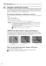
*4.
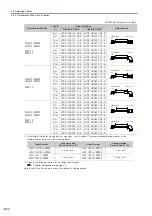
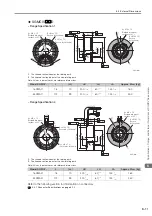
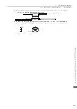
The thrust loads and moment loads that are applied while a Servomotor is operating are roughly classified into
the following patterns. Design the machine so that the thrust loads or moment loads will not exceed the values
given in the table.
*5.
If you use an SGD7S-7R6A SERVOPACK and SGMCV-35D Servomotor together, use this value (a derated
value).
Note: For the bearings used in these Servomotors, the loss depends on the bearing temperature. The amount of
heat loss is higher at low temperatures.
Voltage
200 V
Model SGMCV-
04B
10B
14B
08C
17C
25C
16D
35D
Rated Output
*1
W
126
314
440
251
534
785
503
1100
1000
*5
Rated Torque
*1, *2
N
m
4.00
10.0
14.0
8.00
17.0
25.0
16.0
35.0
Instantaneous Maximum Torque
*1
N
m
12.0
30.0
42.0
24.0
51.0
75.0
48.0
105
Stall Torque
*1
N
m
4.00
10.0
14.0
8.00
17.0
25.0
16.0
35.0
Rated Current
*1
Arms
2.0
2.8
4.6
2.4
4.5
5.0
Instantaneous Maximum Current
*1
Arms
6.4
8.9
14.1
8.6
14.7
13.9
16.9
16.0
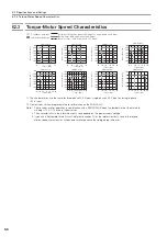
Rated Motor Speed
*1
min
-1
300
300
300
270
*5
Maximum Motor Speed
*1
min
-1
600
600
500
600
400
Torque Constant
N
m/Arms
2.21
3.81
3.27
3.52
4.04
6.04
3.35
7.33
Motor Moment of Inertia
×
10
-4
kg
m
2
16.2
25.2
36.9
56.5
78.5
111
178
276
Rated Power Rate
*1
kW/s
9.88
39.7
53.1
11.3
36.8
56.3
14.4
44.4
Rated Angular Acceleration Rate
*1
rad/s
2
2470
3970
3790
1420
2170
2250
899
1270
Heat Sink Size
mm
350
×
350
×
12
450
×
450
×
12
550
×
550
×
12
Allowable Load Moment of Inertia
(Motor Moment of Inertia Ratio)
25
times
40
times
45
times
15
times
25
times
25
times
10
times
15
times
With External Regenerative Resistor
and Dynamic Brake Resistor
*3
25
times
40
times
45
times
15
times
25
times
25
times
10
times
15
times
Allowable
Load
*4
Allowable Thrust
Load
N
1500
3300
4000
Allowable Moment
Load
N
m
45
55
65
92
98
110
210
225
F
F
L
F
L
Where F is the external force,
Thrust load = F + Load mass
Moment load = 0
Where F is the external force,
Thrust load = F + Load mass
Moment load = F × L
Where F is the external force,
Thrust load = Load mass
Moment load = F × L


