


5.4 External Dimensions
5-14
5.4
External Dimensions
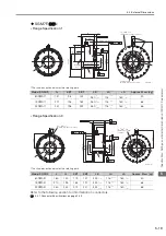
SGM7F-
A
•
Flange Specification 1
*1.
The shaded section indicates the rotating parts.
*2.
The hatched section indicates the non-rotating parts.
Note: Values in parentheses are reference dimensions.
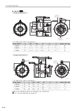
•
Flange Specification 4
*1.
The shaded section indicates the rotating parts.
*2.
The hatched section indicates the non-rotating parts.
Note: Values in parentheses are reference dimensions.
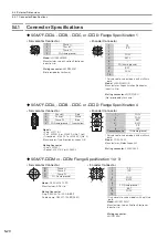
Refer to the following section for information on connectors.
5.4.1 Connector Specifications
Model SGM7F-
L
(LL)
LB
LH
LA
Approx. Mass [kg]
02A
A11
61
(52.7)
100
15
60
2.5
05A
A11
96
(87.7)
100
15
60
4.5
07A
A11
122
(113.7)
100
15
60
5.5
Model SGM7F-
L
(LL)
LB
LH
LA
Approx. Mass [kg]
02A
A41
61
(52.7)
100
15
60
2.5
05A
A41
96
(87.7)
100
15
60
4.5
07A
A41
122
(113.7)
100
15
60
5.5
6 × M4 × 6
(Divided into equal
sections at 60°.)
(2 × M5 × 8)
(For use by
Yaskawa)
*1
*2
23.4
25.7
25
.4
25.7
(1)
1.5
6.8
90
R26
(LL)
L
(19.1)
(0.1)
A
0.07
B
0.07 dia.
LB dia.
(82 dia.)
92 dia.
99.5 dia.
100 dia.
LA dia.
(38 dia.)
LH dia.
53 dia.
Unit: mm
B
0.02
A
0.04
6 × M5 × 8
(Divided into equal
sections at 60°.)
0
-0.035
+0.4
0
0
-0.030
0
-0.035
+0.4
0
0
-0.030
0
-0.035
+0.4
0
0
-0.030
6 × M4 × 6
(Divided into
equal sections
at 60°.)
6 × M5 × 8
(Divided into equal
sections at 60°.)
(2 × M5 × 8)
(For use by
Yaskawa)
1.5
6.8
(LL)
L
300
50
(35)
18
43.5
24.5
10
(22)
A
0.04
0.07
B
A
0.07 dia.
92 dia.
92 dia.
(0.1)
LB dia.
(82 dia.)
*1
53 d
ia.
Unit: mm
B
0.02
*2
(1)
100 dia.
99.5 dia.
LA dia.
(38 dia.)
LH dia.
92 dia.
0
-0.035
+0.4
0
0
-0.030
0
-0.035
+0.4
0
0
-0.030
0
-0.035
+0.4
0
0
-0.030