


5.3 Specifications and Ratings: Medium Capacity
5.3.2 Ratings
5-10
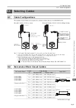
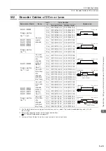
*4.
The given values are for when the Servomotor shaft is mounted horizontally and shock or vibration is applied in
the directions shown in the following figures.
The strength of the vibration that the Servomotor can withstand depends on the application. Check the vibration
acceleration rate.
5.3.2
Ratings
*1.
These values are for operation in combination with a SERVOPACK when the temperature of the armature wind-
ing is 20
°
C. These are typical values.
*2.
The rated torques are the continuous allowable torque values at a surrounding air temperature of 40
°
C with a
steel heat sink of the dimensions given in the table.
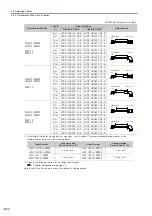
*3.
The thrust loads and moment loads that are applied while a Servomotor is operating are roughly classified into
the following patterns. Design the machine so that the thrust loads or moment loads will not exceed the values
given in the table.
Note: For the bearings used in these Servomotors, the loss depends on the bearing temperature. The amount of
heat loss is higher at low temperatures.
Side to side
Front to back
Vertical
Shock Applied to the Servomotor
Vibration Applied to the Servomotor
Vertical
Voltage
200 V
Model SGM7F-
45M
80M
1AM
80N
1EN
2ZN
Rated Output
*1
W
707
1260
1730
1260
2360
3140
Rated Torque
*1, *2
N
m
45.0
80.0
110
80.0
150
200
Instantaneous Maximum Torque
*1
N
m
135
240
330
240
450
600
Stall Torque
*1
N
m
45.0
80.0
110
80.0
150
200
Rated Current
*1
Arms
5.8
9.7
13.4
9.4
17.4
18.9
Instantaneous Maximum Current
*1
Arms
17.0
28.0
42.0
28.0
56.0
56.0
Rated Motor Speed
*1
min
-1
150
150
Maximum Motor Speed
*1
min
-1
300
300
250
Torque Constant
N
m/Arms
8.39
8.91
8.45
9.08
9.05
11.5
Motor Moment of Inertia
×
10
-4
kg
m
2
388
627
865
1360
2470
3060
Rated Power Rate
*1
kW/s
52.2
102
140
47.1
91.1
131
Rated Angular Acceleration Rate
*1
rad/s
2
1160
1280
1270
588
607
654
Heat Sink Size
mm
750
×
750
×
45
Allowable Load Moment of Inertia
(Motor Moment of Inertia Ratio)
3 times
With External Regenerative Resistor and
External Dynamic Brake Resistor
3 times
Allowable
Load
*3
A
mm
33
37.5
Allowable Thrust Load
N
9000
16000
Allowable Moment Load
N
m
180
350
F
F
L
F
L
Where F is the external force,
Thrust load = F + Load mass
Moment load = 0
Where F is the external force,
Thrust load = F + Load mass
Moment load = F × L
Where F is the external force,
Thrust load = Load mass
Moment load = F × (L + A)
A (Refer to the
values in the
table.)


