background image

B95W

Description

05_Beschreibung_en.fm - V1.0 - 1.8.17

97 / 306

5

11

Submenu, 

display basic 
settings

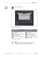
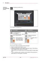
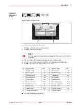
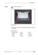
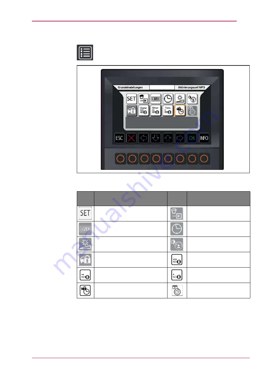
Activate by selecting menu

Fig. 5-32 Submenu, display basic settings

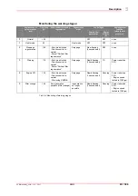
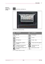
Tab. 5-13 Pictograms display basic settings

Sym-
bol

Description

Sym-
bol

Description

Set units

Set language

Set date

Set time

Set brightness

Set day - night

Enable/disable immobilizer 
(optional)

Change owner PIN (optional)

Change driver PIN (optional)
Immobilizer (optional)

Change transport PIN 
(optional)

Set immobilizer activation time 
(optional)

Reset day trip counter

Owner

Driver

Trans

Содержание B95W

Страница 1: ...Operating Instructions MUB67ENMA00100 5780213263 01 01 2017 Mobile Excavator B95W Original Operating Instructions From Product Identification Number TW09540100 ...

Страница 2: ......

Страница 3: ...zard symbols 16 3 2 2 Mandatory signs 17 3 3 Locations of safety signs 19 3 3 1 Safety sign 22 3 3 2 Pictograms 26 3 4 Personal safety 28 3 4 1 Personal safety gear 28 3 5 Workspace safety 29 3 5 1 General work zone regulations and safe work practices 29 3 5 2 Switching off the machine and securing it against restarting 29 3 6 General safety notes 30 3 7 Operation 31 3 8 Hazard zone 32 3 9 Transpo...

Страница 4: ...loading equipment emergency function 46 3 25 3 Releasing the residual pressure 46 3 26 Emergency exit 46 4 Initial installation and settings 47 4 1 Initial instruction 47 4 1 1 Hand over the machine and instruct the operator 47 5 Description 49 5 1 Type plate 49 5 2 Overview of machine 51 5 2 1 Guards 52 5 2 2 Engine 54 5 2 3 Hydraulic system 57 5 2 4 Electrical system 58 5 2 5 Fuse and relay box ...

Страница 5: ...tem 162 6 7 8 Hydraulic oil tank 166 6 7 9 Hydraulic oil return filter 171 6 7 10 Bleeding the plunger cylinders 173 6 7 11 Hose rupture safety valves of support legs 174 6 7 12 Steering 175 6 7 13 Axles 175 6 7 14 Wheel hub 180 6 7 15 Wheels 182 6 7 16 Brakes 183 6 7 17 Swing gear 187 6 7 18 Swing connection 188 6 7 19 Electrical equipment 192 6 7 20 Cab ventilation dust filter 199 6 7 21 Windshi...

Страница 6: ...ecovery 262 8 2 Loading the machine using a crane 266 8 3 Loading the machine onto a truck 268 8 4 Transporting the machine 269 9 Technical data 271 9 1 Views 271 9 1 1 Digging envelopes 271 9 1 2 Envelope circle 275 9 1 3 Lateral parallel adjustment 276 9 1 4 Articulated boom excavators adjusted 276 9 2 Technical data 277 9 2 1 Operating data 277 9 2 2 Equivalent vibration values 278 9 2 3 Drive ...

Страница 7: ... 9 2 15 Other equipment 289 10 Troubleshooting 291 10 1 Who is allowed to rectify malfunctions 292 10 2 Before troubleshooting and fault rectification 292 10 3 Troubleshooting and fault rectification 293 10 3 1 General malfunctions 293 10 3 2 Immobilizer faults 299 11 Index 301 ...

Страница 8: ...B95W Table of contents 6 306 1 01_Inhaltsverzeichnis_enIVZ fm V1 0 1 8 17 10 ...

Страница 9: ...t always be available at the deployment location of the machine Technical modifications Items described in these operating instructions are subject to change without prior notification Copyright These operating instructions are protected by copyright It must not be copied disseminated or used for competitive purposes either fully or in part without prior written permission Definition of target gro...

Страница 10: ...chinery and display knowledge and understanding of all safety related instructions sources of danger and safety precautions have received training and instruction concerning what to do in the event of a malfunction have read through the entire documentation in particular the operating instructions and be capable of applying the information contained therein be familiar with the hand signals for gu...

Страница 11: ...ers must possess the relevant national heavy goods vehicle license possess the relevant national operating license for this machine should they be required to drive it during loading Guides must be easily recognizable e g by means of reflective clothing remain in the operating staff s field of vision only work in the capacity of a guide and may not be entrusted with any other tasks have the necess...

Страница 12: ...national license for the moving of heavy goods with a crane Waste disposal staff must be employed by an authorized waste disposal company as per national regulations have the necessary knowledge to dispose of materials safely and in an environmentally friendly manner be informed about structural particularities residual energy by service staff who are authorized by the manufacturer ...

Страница 13: ...Signal word for danger level 3 Type and source of danger 4 Possible consequence of danger 5 Measures for hazard prevention 6 Safety symbol Notes Abbreviations employed DANGER Type of danger Consequence of danger Z Action against danger 3 6 1 2 5 4 Notice This symbol is employed for information containing important notes about correct use and or how to proceed Non compliance may lead to malfunction...

Страница 14: ... vehicle s road license The machine is only permitted on public roads with a specific or general operating permit to this end Strict compliance with the operating and maintenance instructions and the performance of maintenance work as well as adherence to the maintenance intervals is also part of intended use The operator must also follow the enclosed operating instructions for externally supplied...

Страница 15: ... sound power level 98 0 dB A 5 Guaranteed sound power level 100 0 dB A 6 Applied harmonized standards EN ISO 12100 EN 474 1 EN 474 5 7 Document editor who is authorized to compile technical documentation Ravindra Bachalli Kraftwerkstraße 4 74564 Crailsheim Germany 8 Conformity evaluation process according to directive 2000 14 EC as well as voluntary prototype testing by DGUV German Social Accident...

Страница 16: ...9 in the Federal Republic of Germany must also be complied with when operating the earth moving machine In addition to the operating instructions legal regulations governing road safety and accident prevention measures must also be observed Such duties may also apply in respect of e g handling hazardous materials or the wearing of personal protective equipment Furthermore safety laws governing wor...

Страница 17: ...on Danger Indicates an imminently hazardous situation which if the safety regulations are not observed will result in serious injury or death Warning Indicates a potentially hazardous situation which if the safety regulations are not observed will result in serious injury or death Caution Indicates a potentially hazardous situation which if the safety regulations are not observed may result in pro...

Страница 18: ...nary measures are not taken high electric voltages high load currents on terminals capacitors housing parts and printed circuit boards may lead to considerable property damage physical injuries or death Warning of risk of explosion If the required precautionary measures are not taken explosive gases or contact with caustic acids may lead to substantial damage to property equipment personal injury ...

Страница 19: ...ntal damage 3 2 2 Mandatory signs The mandatory signs used in this manual and on the machine require the following safety measures Work with protective clothing If the required protective clothing is not worn during work personal injury may result Work with protective gloves If the required protective gloves are not worn during work hand injuries may result Work with protective goggles If the requ...

Страница 20: ...rk serious personal injury may result Work with foot guards If the required foot guards are not worn during work injuries to the feet may result Work with a life jacket If the required life jacket is not worn during work serious personal injury may result Work with a safety belt If the required safety belt is not worn during work personal injury may result Work with protective headgear If the requ...

Страница 21: ...ty belt 3 Risk of injury from front window swinging open 4 Risk of injury from moving machines 5 Electric shock from contact with the power lines 6 Read and understand the operator s manual 7 Risk of fatal injury from the rotating uppercarriage 8 Risk of injury burns from exploding battery or contact with battery acid near battery 9 Risk of arms and hands becoming entangled in rotating parts 10 Ri...

Страница 22: ...de view from right 1 Risk of fatal injury from the rotating uppercarriage 2 Risk of arms and hands becoming entangled in rotating parts 3 Risk of injury from the articulated area 4 Risk of injury from the excavator arm or the dipper 5 Risk of arms and hands becoming entangled in rotating parts ...

Страница 23: ... from in front 1 Risk of scalding from hot pressurized fluids 2 Risk of injury from pressurized containers 3 Risk of burning from hot surfaces 4 Risk of injury from the articulated area 5 Risk of injury from fluids spraying out which may get underneath the skin 6 Emergency exit 4 4 5 1 2 3 1 2 3 5 6 6 ...

Страница 24: ...otating parts Move attachment into resting position before leaving vehicle turn off vehicle and remove key Maintain sufficient distance from rotating parts Switch machine off prior to conducting maintenance work Risk of arms and hands becoming entangled in rotating parts Risk of injury by falling from the machine Turn the machine off and remove the key prior to maintenance work Use access steps an...

Страница 25: ...xcavator arm when it is moving Keep well clear of the machine when in operation Risk of burning from hot surfaces Risk of injury from fluids spraying out which may get underneath the skin Do not touch hot surfaces Allow the machine to cool before performing any maintenance work Keep well clear of leaks and blowholes Release the pressure before disconnecting hydraulic lines ...

Страница 26: ...essure prior to maintenance work Do not weld or spot weld the tanks or battery Keep flames and other hot sources away from the containers and the battery No naked flames or sparks Wear protective gear Adhere to the operating instructions Riskofscalding from hot pressurized fluids Tipping risk Do not unscrew the cover of the combined cooler in a heated state Always fasten the safety belt ...

Страница 27: ... have gone missing Use mild detergents and water to clean the safety signs Do not use any cleansers that contain solvents Always specify the machine serial number and language when ordering safety signs Risk of injury from falling window Risk of injury caused by incorrect operations or maintenance Secure window Read and understand the operator s manual Tipping risk Emergency exit Activate overload...

Страница 28: ...el Fuel level Hydraulic oil Hydraulic oil level Coolant temperature Hydraulic oil filter clogging indicator Heating ventilation blower Windshield wiper wash wipe system Operating hours counter Potentiometer Working lights Air filter indicator Rotating beacons Hydraulic hammer Dozer blade Working hydraulics shut off Float position dozer blade OFF switch overload warning device Travel speed SLOW Tra...

Страница 29: ... 1 Pictograms Bucket change over ISO to SAE change over Boom height limitation Grease gun Suspension points for loading by crane Do not use for loading of cranes Lashing points First aid kit Signal horn Fire extinguisher Pictogram Description Pictogram Description ...

Страница 30: ... Maintenance personnel Protective gloves Safety glasses Hearing protectors Safety footwear Protective clothing Service personnel Protective gloves Safety glasses Hearing protectors Safety footwear Protective clothing Carriers Protective gloves Safety glasses Safety footwear Protective clothing Guides Reflective clothing Personnel responsible for attaching loads Protective gloves Safety glasses Saf...

Страница 31: ...ular locations tunnels adits quarries pontoons contaminated areas etc must likewise be observed The plant operator and the machine driver are responsible for ensuring that the safety regulations are upheld The operator must always familiarize himself with the local regulations 3 5 2 Switching off the machine and securing it against restarting Ensure all the following safety instructions are read p...

Страница 32: ...hat the engine hood is closed and never open it when the machine is running Close all doors windows hoods flaps or secure these while they are open to prevent unintended closing During work Never make any safety features ineffective and do not remove any safety features Wear protective clothing for operation Take off rings scarves open jackets Protective goggles safety boots helmets protective glo...

Страница 33: ... vehicle Close all doors or secure these while they are open to prevent them from slamming shut accidentally The uppercarriage and undercarriage must be aligned When opening or closing doors windows hoods and lids use the fitted handles grips Make sure that the operator s stand handles access steps and other surfaces of the machine that have to be stepped on are kept free of dirt grease oil ice an...

Страница 34: ...ody is in the danger zone The machine operator must give a warning signal to persons who may be in danger Stop work with the machine if persons remain in the danger zone despite the warning To ensure no danger of crushing a sufficient safety distance min 0 5 m must be kept from solid objects e g buildings excavation slopes scaffolding other machines etc If the safety distance cannot be kept fence ...

Страница 35: ...y of the range of motion of the work equipment There is a constant danger of collisions involving the work equipment and cab 3 9 Transporting persons Never transport persons on or with the machine 3 10 Stability The machine must be used driven and operated in such a manner that its stability against overturning is ensured at all times Match the travel speed to the local conditions Do not exceed th...

Страница 36: ...tability specifications are based on ground that is level solid and even All stability calculations must be made with a horizontally positioned machine on even and solid ground If the machine is operated under conditions that do not meet this requirement such as loose and uneven ground no horizontal position side loads etc these conditions must be taken into consideration by the operator Never exc...

Страница 37: ...g them about Do not drive and apply brakes jerkily The carrying capacity of bridges cellar roofs vaults etc must be verified before the earth moving machine can drive over them Check the clear dimensions of structures before entering into subways tunnels etc Always ensure that your speed and manner of driving is appropriate to the circumstances Machine operators have sole responsibility for the wa...

Страница 38: ...ng under the risk of falling objects If dangers are posed by falling objects only use the machine if the driver s seat is protected by a canopy roof FOPS Falling Object Protection Structure A front guard must be employed if there is a risk of materials breaking through into the cab When working in front of walls with stacks of materials for example position the machine in such a way that the drive...

Страница 39: ...their protective coverings are encountered unexpectedly or damaged stop work immediately and inform the supervisor In case of arcing adhere to BGR 500 K 2 12 3 12 Maintain a safe distance from the power lines 3 16 Working in the vicinity of overhead power lines If the machine is being used in the vicinity of overhead power lines and trolley wires a safety distance which varies depending on the nom...

Страница 40: ...rhead power lines and trolley wires the plant operator must consult the proprietor or operator of the overhead lines to identify other safety precautions that will prevent current overspill Such measures could include Switching off the current Re routing the overhead line Wiring Limitation of the working range of the machine 3 17 Operating in enclosed spaces If machines are to be used in enclosed ...

Страница 41: ... off the working hydraulics Before exiting the machine shut down the engine and secure it against unauthorized restarting e g by pulling out the ignition key or disconnecting the battery if necessary Disconnect the machine s power supply by flicking the battery isolator For longer periods of work stoppage Relieve the residual pressures Switch off the battery isolator switch Secure the machine agai...

Страница 42: ... equipment Only attach loads which do not exceed the carrying capacity of the machine and the lifting equipment Please note the overload warning device Loads must only be attached to the designated load hooks in such a way that they cannot slip or fall out Do not exceed the permissible load for the load hook Do not carry loads over persons Machines may only move with an attached load if the path o...

Страница 43: ...e the hydraulic system before starting maintenance and repair work on it With the engine turned off lower the loading equipment to the ground and actuate all hydraulic operating levers until there is no more pressure in the hydraulic system Always secure the machine with wheel chocks to prevent rolling when working on or especially under the machine Keep any third parties clear of the machine s da...

Страница 44: ...und terminal of the welding equipment is connected directly to the part being welded Never make any modifications to protective structures ROPS FOPS e g by welding or drilling them In the event of plastic deformations and or cracks in the load bearing elements of protective structures ROPS TOPS FOPS they must be replaced Alterations e g welding of the hydraulic system are only to be undertaken wit...

Страница 45: ...epairs must therefore be carried out by your dealer s customer service Within the warranty period damage claims can only be lodged if the specified intervals for maintenance and inspection work have been complied with Even after the end of the warranty period regular maintenance must be performed to keep the machine in good working order at all times and to ensure that it enjoys a reasonable servi...

Страница 46: ...ground as well as the machine with wedges and by fastening it at the lashing points Before setting off the route to be taken must be examined The roads must be wide enough entrances and passages under bridges must be large enough and roads and bridges must have sufficient carrying capacity Use and appropriate flat bed trailer as per the machine data dimensions weight Keep the loading equipment as ...

Страница 47: ...l shape of the installed hose Leaks Damage to the hose fixtures or connectors between the fixtures and hose Do not search for leaks on the hydraulic lines merely using your hands use cardboard or wood to locate them In the event of any liquids that are spat out getting under the skin a doctor who is experienced with this kind of injury must be consulted within a matter of hours Always wait until t...

Страница 48: ...ower the loading equipment 3 25 3 Releasing the residual pressure Shut down the engine Fold the left console armrest down Turn the ignition key to position 1 Activate the working hydraulics on the keypad Actuate all the hydraulic operating elements right and left joysticks with dials control pedals until the pressure has been released 3 26 Emergency exit The front windshield serves as an emergency...

Страница 49: ...l training on the machine Items which are particularly important include Accident Prevention Regulations published by the employer s liability insurance associations in the user s country Technical data Control indicating and warning elements Checks before commissioning the machine Engine running in instructions Starting and shutting down the engine Explanation of the hydrostatic travel drive Driv...

Страница 50: ...d texts Explain that spare parts orders must always include details of the machine type vehicle identification number Fz Id Nr parts designation complete spare part number quantity delivery address etc Warranty Explain the warranty conditions Explain the inspection cards with reference to the maintenance and inspection plan Fill in the warranty handing over card correctly and send it back to us ...

Страница 51: ... The vehicle type and vehicle identification number are stamped on the type plate Fig 5 1 Type plate 1 Vehicle type 2 Vehicle identification number Notice Please state the vehicle type and vehicle identification number when making inquiries or placing orders and in all written correspondence ...

Страница 52: ...B95W Description 50 306 5 05_Beschreibung_en fm V1 0 1 8 17 11 ...

Страница 53: ... 11 5 2 Overview of machine Fig 5 2 Overview of machine 1 Shutdown 2 Water and hydraulic oil cooler 3 Cabin 4 Boom 5 Intermediate boom 6 Dipperstick 7 Bucket 8 Slewing column 9 Outrigger 10 Diesel Tank 11 Hydraulic fluid tank 12 Pumps 13 Battery 14 AdBlue tank ...

Страница 54: ... 11 5 2 1 Guards Fig 5 3 Guards 1 Rear hood 2 Side hood engine hood folding 3 Maintenance cover maintenance ladder folding 4 Diesel tank hydraulic system cover folding 5 Fuse and relay box cover 6 AdBlue tank 7 AdBlue filter element 8 Diagnostic interface cover ...

Страница 55: ...out maintenance and repair work always open the guards far enough such that they stay open on their own Located under the side maintenance cover Battery Refueling pump AdBlue tank Located under the side cover Engine Radiator cooling system Pump gear Air intake system Alternator The following is housed beneath the diesel tank hydraulic unit Fuel tank Hydraulic oil tank Located under the rear hood P...

Страница 56: ...5 2 2 Engine Fig 5 4 Engine 1 Sealing cap 2 Generator 3 Engine 4 Engine cooling system inlet 5 Oil drain plug 6 Engine oil filters 7 Oil dip stick 8 Engine cooling system outlet 9 Fuel pre cleaner 10 Fuel tank 11 Exhaust system 12 Fuel filter 13 Electric fuel pump ...

Страница 57: ...ble when the side hood is open or the maintenance stairs side hood are folded down Automatic engine shutdown optional The engine shuts down automatically if the following both occur for longer than 10 minutes the park brake is engaged and the machine is stationary The time can be set on the display ...

Страница 58: ...B95W Description 56 306 5 05_Beschreibung_en fm V1 0 1 8 17 11 ...

Страница 59: ... 8 17 57 306 5 11 5 2 3 Hydraulic system Fig 5 5 Hydraulic system 1 Hydraulic fluid tank 2 Distribution 3 Pump auxiliary drive The following are driven hydraulically Drive transmission Boom movement Bucket movement Brakes Uppercarriage Dozer blade ...

Страница 60: ...95W Description 58 306 5 05_Beschreibung_en fm V1 0 1 8 17 11 5 2 4 Electrical system Fig 5 6 Electrical system 1 Battery circuit breaker 2 Battery 3 Generator 4 Diagnostic interface 5 Fuses and relays 3 ...

Страница 61: ...erator supplies the onboard power supply system with a voltage of 12 V You can disconnect the entire machine from the power supply with the main battery switch e g for maintenance work Notice The control unit will remain active another 40 seconds or so to save the system data and then it will turn itself off This process can last up to 2 minutes for engines with an SCR system given that the SCR li...

Страница 62: ...ay F14 5 A Interior light radio F5 5 A Power supply SPU F15 15 A Heating control F6 10 A Hazard warning lights F16 20 A Heater fan F7 20 A Low beam light high beam light F17 5 A Supplementary heating timer F8 15 A High beam F18 20 A Supplementary heating F9 15 A Rotating beacons F19 15 A Telematic system F10 15 A Front working floodlight F20 5 A Spare Fuse block A2 terminal 15 F1 5 A Fuel pump rel...

Страница 63: ...ght F13 15 A Heating control F4 5 A Joystick left F14 5 A Central lubrication system F5 5 A Switch console F15 20 A Central lubrication system F6 15 A Changeover ISO SAE F16 20 A Refueling pump F7 5 A Load warning F17 20 A Comfort seat F8 5 A Hydraulic oil level F18 10 A Mirror heating F9 5 A Auto idling system F19 10 A Telematic system F10 10 A Direction indicators F20 5 A Spare Fuse block A4 lig...

Страница 64: ...2 Hazard warning lights Relay block A6 K1 Rotating beacons K4 Working floodlight boom K2 Front working floodlight K5 Changeover ISO SAE K3 Rear working floodlight K6 Mirror heating Relay block A7 K1 Windscreen washer K2 Heater fan Relay block A8 K1 K4 AdBlue heating pressure line K2 AdBlue heating system K5 AdBlue heating return pipe K3 AdBlue heating supply module K6 AdBlue heating Suction Hose ...

Страница 65: ...ibung_en fm V1 0 1 8 17 63 306 5 11 Fig 5 9 Configuration of main fuses Tab 5 3 Configuration of main fuses Pos Amps Assigned to Pos Amps Assigned to Main fuses F01 80A Main fuses F02 80A Pre heating F04 30A Starter motor sensor ...

Страница 66: ...international quality and safety standards Fig 5 10 Driver s seat 1 Handle for adjusting seat depth 2 Handle for adjustment of cushion angle 3 Right arm rest left arm rest 4 Option Switch for heated seat 5 Handwheel for lumbar support 6 Handle for tilting backrest 7 Handle for combined height and body weight adjustment Optional Lever for weight adjustment 8 Handle for longitudinal adjustment 1 2 3...

Страница 67: ...s operation for additional control circuits 9 2 Actuate dial for additional control circuit 1 9 3 Articulated boom changeover 10 Move forward backward 11 Engine speed setting manual throttle 12 Power socket 12 V 13 Optional radio 14 Right hand support 15 Left hand support 16 Joystick left 16 1 Signal horn 16 2 Actuate dial for auxiliary control circuit 2 16 3 Slewing pressure switch 17 Steering wh...

Страница 68: ...termediate lubrication optional 26 Switch quick attachment system optional 27 Switch hazard warning lights 28 Switch steering direction reversal optional 29 Switch manual transmission setting I II optional 30 Switch axle lock 31 Switch travel pedal optional 32 Parking brake switch 33 Switch power tilt optional 34 Switch plate float position optional Notice The left arm rest also serves as the left...

Страница 69: ...on optional 21 Spare 29 Gearbox ratios I II optional 22 Spare 30 Pendulum axle lock 23 Float position front plate optional 31 Foot throttle optional 24 Rear fog light optional 32 Park Brake 25 Central lubrication optional 33 Power tilt optional 26 Quick attachment system optional 34 Plate float position optional 27 Warning light ...

Страница 70: ...u immobilizer The machine is mainly operated via the keypad by pressing the individual function buttons The corresponding display appears when these functions are operated Front working floodlight Working floodlight rear optional Rotating beacon optional Windshield wiper Washer wiper Automatic heating and air conditioning Heater fan Increase inside cab temperature Lower inside cab temperature Acti...

Страница 71: ...Step 2 press function button twice Continuous operation J Two LEDs are illuminated Heating and A C system The heating and air conditioning system has two switch settings Step 1 press function button once Activation of the heating and air conditioning system J One LED is illuminated Step 2 press function button twice Deactivation of the A C system optional The temperature control remains active J N...

Страница 72: ...hing Pos Description Pos Description 1 Time 9 Coolant temperature gauge 2 Date 10 Display bar for activated functions 3 Tachometer 11 Menu control icons 4 Company logo 12 Function buttons 5 Operating hour meter daily counter 13 Icons Machine monitoring see table below 6 Operating hours total 14 Display direction of travel neutral setting 7 Icons Engine monitoring see table below 15 Fuel level indi...

Страница 73: ...ttery charge indicator Pre heating Multi icons bottom right Engine diagnostics Condensed water in the fuel filter Coolant level Air filter maintenance Particle filter regeneration optional Ash lamp optional AdBlue particle filter Sym bol Description Sym bol Description Direction indicator Trailer indicator light Travel direction forward reverse Neutral position direction of travel High beam Park b...

Страница 74: ...ine error engine error occurs Fig 5 15 Display error message When errors occur please contact Yanmar customer service If an error is displayed troubleshoot immediately Ignoring error messages can lead to serious damage to the machine and its engine If the error message is ignored continually the engine may switch off automatically after a certain period ...

Страница 75: ...the diagnostic interface for deactivating the shut off procedure Fig 5 16 Engine override 1 Engine bypass switch CAUTION Danger as a result of existing error Risk of engine damage Z Only activate engine bypass in the event of danger Z For normal operation you must disable engine bypass again Z Enabling of engine override is recorded in the engine control unit and will result in the loss of warrant...

Страница 76: ...the main menu you can press a button to jump into the corresponding submenu The submenus are used for navigation and to process figures User guidance is provided automatically via a change in color of the frame around the symbol or of the symbol itself Fig 5 18 Appearance of the function keys when activated 1 Function inactive 2 Function selected 3 Function confirmed 4 Function activated 1 2 3 4 ...

Страница 77: ... menu Fig 5 19 Display main view 1 Submenu machine functions 2 Submenu machine options 3 Submenu machine adjustments 4 Submenu ventilator control inactive 5 Submenu air conditioning control 6 Submenu rear view camera 7 Submenu diagnosis 8 Submenu display basic settings ...

Страница 78: ...ESC back 5 Delete 6 Cursor to the left 7 Cursor to the bottom or Decrease value of variables 8 Cursor to the top or Increase value of variables 9 Cursor to the right 10 Saving 11 Information provided When the submenu is opened the cursor always appears at the top left The function required is selected with the cursor keys and then confirmed by pressing OK Descriptions of the individual functions a...

Страница 79: ...al Bucket changeover optional ISO SAE changeover optional ECO mode optional Particle filter regeneration optional Auto idle optional Ash lamp optional Display for position of front axle steering equipment position optional Display for position of rear axle steering equipment position optional Period for automatic engine shutoff optional Notice When in inactive state the submenu is locked Notice Th...

Страница 80: ...n This causes the front and rear axles to misalign reducing soil damage Press OK to turn the mode on off The mode is only activated when the front axle in centered When turning off the mode only deactivates once the rear axle is centered The display will show when the centering of the axle is detected Notice The All wheel fast option enables you to also activate the mode in hare mode or in second ...

Страница 81: ...be turned on An icon in the main menu will show when the mode is activated When the ECO mode is active the auto idle and automatic engine shutoff functions are turned on Equally when the ECO mode is deactivated the auto idle and automatic engine shutoff functions are turned off Press OK to turn the mode on off Auto idling system When the function is active it is indicated on the display by an icon...

Страница 82: ... minutes will deactivate the engine shutoff The setting Time to automatic engine shutoff is selected via a bar chart By moving the cursor up or down the value can be adjusted in increments of 3 minutes The value is then saved permanently Select OK to go to the settings menu where you can adjust the length of time for the automatic engine shutoff between 0 to 30 minutes Notice First though the ECO ...

Страница 83: ... at 100 If the heat mode fails to reduce the carbon black load sufficiently the filter will keep accumulating carbon black and eventually stoppage regeneration will be required When stoppage regeneration is requested the control light Particle filter regeneration turns on The stoppage regeneration is the last option for regenerating the filter if all prior attempts to regenerate the filter have fa...

Страница 84: ...th power reduction of 30 engine speed is limited to 1200 rpm Level 5 Filter change Active if relative carbon black load at 156 Filter overload If despite the engine OFF message the engine is still in operation and the filter continues to accumulate load regeneration is no longer possible At this point the filter must be replaced The engine OFF level limits the engine speed to 1200 rpm Now the mach...

Страница 85: ... break locked Direction switch in neutral Select Particle filter regeneration Stoppage Slow flashing 2 second beat OFF none 3 Warning 110 Park break locked Direction switch in neutral Select Particle filter regeneration Stoppage Rapid flashing 1 second beat TO Power reduction 30 4 Engine Off 125 Park break locked Direction switch in neutral Start using SERDIA Stoppage Rapid flashing 1 second beat ...

Страница 86: ...ust be replaced J The Ash control light icon ash indicator in the engine monitoring icon bar flashes yellow Filter replacement warning J If the filter replacement request is ignored then the Ash lamp icon starts to flash once 105 of the ash load is reached Additional loading of the filter with ash leads to shorter regeneration intervals and increasing exhaust gas back pressure Tab 5 9 Icon meaning...

Страница 87: ...he engine increases its speed to approx 1700 rpm for the duration of the regeneration WARNING Danger from hot surfaces and exhaust gases During regeneration exhaust gas temperatures of 650 C and higher may arise at the exhaust pipe The surface temperature of the diesel particulate filter module with insulating sheath reaches 200 C on average Risk of burns Danger of setting fire to objects in the v...

Страница 88: ...ter regeneration function is selected again End of stoppage regeneration Once the regeneration process has finished the engine speed will automatically reduce to idling speed If the regeneration has been successful the warning buzzer sounds three times once more and the particle filter regeneration control light goes out Notice In an emergency the operator can cancel the regeneration using the exh...

Страница 89: ...ion Sym bol Description Activation dozing blade front optional Enable rear support plate optional Enable switching valve control circuit I optional Enable switching valve control circuit II optional Turn off driving alarm optional Backup camera automatically off optional Notice You can reset all these machine options by turning off the ignition terminal 15 except for the dozer blade and support bl...

Страница 90: ...ment 1 set number of liters via bar chart Adjustment 2 set number of liters via bar chart Adjustment 3 set number of liters via bar chart How to set the liter quantity for individual control circuits Select the desired control circuit with the cursor Change the number of liters by clicking on the up or down arrows which changes the size of the bar in the chart ...

Страница 91: ...ng on the up or down arrows which changes the size of the bar in the chart Sym bol Description Sym bol Description Activation reversible fan Deactivation reversible fan Fan is turning at maximum speed Reversible fan cycle time Notice The cycle time for the reversible fan can be set in increments of 0 5 within a range from 0 5 to 5 hours When delivered the reversible fan is switched on once an hour...

Страница 92: ...r down arrows which changes the size of the bar in the chart These functions can also be carried out on the keypad with the corresponding keys The air conditioning system optional can be switched off by pressing the appropriate key on the keypad a second time Sym bol Description Sym bol Description Activating heating and air conditioning air conditioning system optional Defrost front windshield Mi...

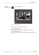
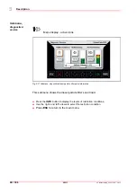
Страница 93: ...e by selecting menu Fig 5 26 Submenu rear view camera Activate the rear view camera in the main view Press the OFF button once J After 30 seconds the camera view changes back to the main view Press the OFF button twice J The camera image remains visible until the OFF button has been pressed again ...

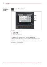
Страница 94: ... Submenu diagnostics service 1 DiagIDs display 2 Service display 3 Sensor quick information The hardware and software status of the sensors is evaluated Select OK in the diagIDs 1 submenu to bring up the selected sensor Select OK in the service display 2 submenu to activate the corresponding sensors Sensor 3 quick information ...

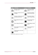
Страница 95: ...and software status of the display Hardware and software status of the A C sensor Hardware and software status of the hydraulic pump sensor Hardware and software status of the gear sensor Service display for the engine sensor Service display for the machine sensor Service display for the display Service display for the A C sensor Service display for the hydraulic pump sensor Service display for th...

Страница 96: ...Submenu diagnostics service Menu display active icons Fig 5 29 Submenu diagnostics service instrument cluster Display mode ID instrument cluster PN Hardware number SN Hardware version number SP Software part number SV Software version Hit ESC to return to the menu ...

Страница 97: ...ics service menu J The units displayed are examples Notice Error messages and engine data are displayed in the menu in either German or English No Engine data Units No Engine data Units 1 Supply voltage V 11 Coolant level 2 Engine speed rpm 12 Air filter warning kPa 3 RPM sensor KW rpm 13 Idling switch OFF 4 RPM sensor NW rpm 14 Foot throttle 5 Fuel pressure kPa 15 Manual throttle 6 Fuel pressure ...

Страница 98: ...ve icons Fig 5 31 Submenu diagnostics diesel particle filter quick information This submenu shows the diesel particle filter s soot load Press the INFO button to display the levels of restriction conditions Use the right and left arrows to select the restriction condition Press ESC to return to the main menu ...

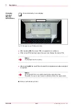
Страница 99: ...13 Pictograms display basic settings Sym bol Description Sym bol Description Set units Set language Set date Set time Set brightness Set day night Enable disable immobilizer optional Change owner PIN optional Change driver PIN optional Immobilizer optional Change transport PIN optional Set immobilizer activation time optional Reset day trip counter Owner Driver Trans ...

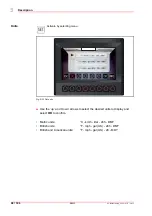
Страница 100: ...11 Units Activate by selecting menu Fig 5 33 Set units Use the up and down arrows to select the desired units to display and select OK to confirm Metric units C km h liter 24h DMY British units F mph gal UK 24h DMY British and American units F mph gal US 24 MDY ...

Страница 101: ...Language Activate by selecting menu Fig 5 34 Set language Use the up and down arrows to select the desire language and confirm by selecting OK Available languages American English Dutch Danish German English French Italian Polish Portuguese Russian Swedish Spanish ...

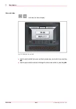
Страница 102: ...m V1 0 1 8 17 11 Time and date Activate via menu display Fig 5 35 Setting the time and date Use the right and left arrows to set the desired value and confirm by selecting OK Use the up and down arrows to change the value and confirm by selecting OK ...

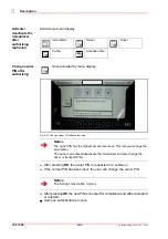
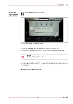
Страница 103: ... and then use the up and down arrows to change the value which changes the bar chart confirm by selecting OK Brightness Set display brightness 1 Alternative day night When the sidelights are turned on terminal 58 the brightness of the display and menu buttons is reduced by around 30 You can also set the brightness and contrast manually in the day night menu 2 Here you can change the display bright...

Страница 104: ...ted in a submenu If the correct PIN has been input the user can change the owner PIN After pressing OK the new PIN is checked for compliance and either accepted or rejected J Same as authorization process Immobilizer Owner Driver Carrier Activation time Owner Driver Trans Notice The owner PIN has the highest access clearance This lets you manage the immobilizer The owner can activate deactivate th...

Страница 105: ... 5 38 Change the driver PIN after authorization After pressing OK the owner PIN is requested in a submenu If the correct PIN has been input the user can change the owner PIN After pressing OK the new PIN is checked for compliance and either accepted or rejected J Same as authorization process Notice The first digit may not be 0 zero Driver ...

Страница 106: ... owner PIN is requested in a submenu If the correct PIN has been input the user can change the owner PIN After pressing OK the new PIN is checked for compliance and either accepted or rejected J Same as authorization process Notice The first digit must be 0 zero Notice The transport PIN is now valid for starting the engine five times Thereafter the owner can choose to authorize another five engine...

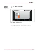
Страница 107: ...fter authorization Once activated by menu display Fig 5 40 Changing activation time after authorization Use the up and down arrows to change the activation time of the immobilizer to between 0 and 60 minutes which changes the bar in the chart Press OK to confirm the selected activation time ...

Страница 108: ...ponder is not read until the mechanical key in the start switch has activated terminal 15 This means that the mechanical locking system has to be opened before the electronic key is checked This makes it impossible to tamper with the immobilizer when the ignition is off Notice The immobilizer is self activating i e there is no need for any additional activation or other kind of action If the mecha...

Страница 109: ...5 off Pull out the master key J The immobilizer system expects the new key to be inserted within 15 seconds Insert the new key into the ignition lock Turn the key to position 1 J The key is registered as a valid key If no key is recognized within 15 seconds the new key procedure ends automatically Setting up multiple new keys Insert the new keys into the ignition lock one after the other Turn the ...

Страница 110: ...accepts no valid keys during this time This procedure prevents the testing of different keys so that the correct key cannot be identified through trial and error If different invalid keys are detected without the ignition lock being brought to position 0 the immobilizer remains activated for 15 minutes and accepts no valid keys Valid keys are only accepted once the 15 minutes have elapsed and the ...

Страница 111: ...1 8 17 109 306 5 11 Reset day trip counter Once activated by menu display Fig 5 41 Reset day trip counter Press OK is activate the icon and reset the day trip counter After confirming the MCU icon lights up briefly the icon becomes inactive again ...

Страница 112: ...e overload warning system on the keypad is activated the standard display changes as follows Fig 5 42 Display when overload warning is active When the overload warning system is on the rev counter is switched to overload warning Notice Display is central when the overload warning function is on ...

Страница 113: ...eriodic maintenance inspection and lubricating tasks The type specific maintenance and inspection plan lists all work to be performed on the machine at regular intervals The relevant maintenance and inspection plans can be found in each set of operating instructions If there is evidence to show that the intervals have not been observed this may restrict the scope of the warranty See chapter 6 3 2 ...

Страница 114: ...event it moving Put the machine into the parking position Uppercarriage in the driving position Do not use aggressive detergents to clean the machine We recommend using commercially available cleaning agents for passenger cars Clean the machine from the ground up with suitable cleaning tools e g high pressure cleaning device telescopic scraper for glass For cleaning purposes park the machine on a ...

Страница 115: ...no components are damaged e g bent radiator grilles Cover any electrical electronic components and connectors when cleaning the engine Clean any mud snow or ice from the machine After wet cleaning always lubricate the machine as specified in the lubrication plan and check all operating cycles and support and travel functions Only clean the engine compartment when the engine is cool and do not let ...

Страница 116: ...spection Once before starting up for the first time 124 Daily tasks Every 10 operating hours or every shift 1 125 Weekly tasks Weekly or after 50 operating hours 1 127 100 operating hours Once after first commissioning 2 128 Every 500 operating hours After every 500 operating hours 128 Every 1000 operating hours After every 1000 operating hours 128 Every 2000 operating hours After every 2000 opera...

Страница 117: ...they actually become absolutely necessary help prevent serious and unexpected damage Resulting damage will also be prevented Oil analysis intervals Regular oil analysis will indicate any developing trends regarding the state of the oil and the machine Based on the results the laboratory recommends the interval for the next sampling 6 3 2 Warranty During the warranty period thorough inspections are...

Страница 118: ...Potential damage to machine Z Do not mix biodegradable oils from different manufacturers Z When changing from mineral to bio degradable hydraulic oils the tank and system must be completely drained cleaned and flushed several times Before changing the oil please ask your Yanmar dealer for further details CAUTION Risk posed by incorrect coolant mixture ratio Potential damage to machine Z See the in...

Страница 119: ...ity lubrication oil and compliance with the prescribed replacement intervals are prerequisites for achieving the specified engine power Notice Only use lubrication oils recommended by the engine manufacturer In the case of engines with after treatment system for exhaust gases only lube oils labeled low ash LA may be used ...

Страница 120: ...ystem Coolant Antifreeze based on ethylene glycol See also engine manufacturer s operating instructions Hydraulics Hydraulic oil or multi grade engine oil HVLP 46 or SAE 10W 40 The following viscosity limit values must be observed according to ASTM 445 at 100 C min 8 mm2 s cSt at 10 C approx 1500 mm2 s cSt Biodegradable hydraulic oil based on synthetic ester Filling according to customer specifica...

Страница 121: ...rature ranges Engine oil hydraulic oil Fig 6 1 Engine oil and hydraulic oil Engine oil in accordance with DQC II DEUTZ Quality Class Hydraulic oil according to DIN 51524 T3 HVLP Ambient temperature Ambient temperature C F 30 25 20 15 10 5 0 5 10 35 30 25 20 15 45 40 22 13 4 5 14 23 32 41 50 95 86 77 68 59 113 104 ...

Страница 122: ...ar oil Steering front axle B95W S transmission switchable circa 1 9 Gear oil Steering front axle B95W B95W AL B95W S wheel hub circa 0 5 Gear oil Rear axle B95W B95W S center housing circa 8 0 Gear oil Left rear axle B95W AL middlehousing circa 7 0 Gear oil Rear axle B95W B95W S wheel hub circa 2 2 Gear oil Steering rear axle B95W AL wheel hub circa 0 5 Gear oil Slewing transmission Circular lubri...

Страница 123: ...ssume liability even within the warranty period CAUTION Risk posed by dirt Dirt in the lubrication system may damage the machine Z Replace defective grease nipples immediately and check if grease passes through Notice The intervals stated apply for single shift operation In case of special operating conditions e g when working on sandy soil the lubrication intervals should be shortened in order to...

Страница 124: ...rease all lubricating points with multi purpose grease WARNING Danger due to heavy load Machine parts may move unexpectedly Risk of serious injuries with fatal consequences Z To lubricate the quick attach system Place the dipper on the ground open the quick attach system the pins must be fully retracted and apply lubricant Then close the quick attach system ...

Страница 125: ... boom 2 X 10 Dipperstick cylinder intermediate boom 1 X 11 Intermediate boom boom 1 X 12 Boom cylinder boom 1 X 13 Intermediate boom cylinder boom 2 X 14 Slewing column boom 1 X 15 Boom cylinder slewing column 1 X 18 Uppercarriage Slewing column 2 X 19 Support leg undercarriage 2 X 20 Support cylinder undercarriage 2 X 21 Support cylinder support leg 2 X 22 Support leg rear support blades pads 2 X...

Страница 126: ...6 Checking maintenance and inspection plan The inspection plan lists all work that needs to be carried out on the machine at regular intervals Work to be carried out by trained dealer service personnel 6 6 1 Initial inspection delivery inspection Fig 6 3 Initial Inspection ...

Страница 127: ...s and fit if necessary 187 9 Top up windshield washer system 200 10 Check AdBlue level 162 11 Check v ribbed belt tension 159 12 Check all hose connectors and brackets for correct fit 13 Check engine mounting 14 Ensure that authorized personnel check the engine monitoring warning system 15 Remove any transport equipment from the vicinity 16 Remove the engine s corrosion protection 17 Perform a tes...

Страница 128: ...126 306 6 06_Wartung und Pflege_en fm V1 0 1 8 17 20 6 6 2 Daily and weekly tasks Inspection and maintenance work to be performed by operating personnel Fig 6 4 Inspection and maintenance plan for daily and weekly tasks ...

Страница 129: ...rom turning 9 Check function of electrical indicating and warning elements as well as the lighting system 187 10 Check all controls are working properly and adjust as necessary 11 Lubricate the machine according to the lubricating chart 122 12 Check electrics Pos Inspection Page 15 Clean cooling fins of the combination cooler In case of visible dust shorten the cleaning intervals 137 16 Check corr...

Страница 130: ...1 2 x 136 4 Fuel pre filter empty the water collection tank If warning system starts empty immediately o x 154 5 Replace the fuel pre filter x x 154 6 Changing the fuel filter x x 156 7 Drain water from fuel tank o o o 158 8 Check suction pipes for damage if damaged replace o o 143 9 Replace air filter main cartridge according to the maintenance indicator x 145 10 Replace air filter safety cartrid...

Страница 131: ...shaft o o 25 Check bushings and pins of working equipment and replace if necessary o o 26 Check that door latches function perfectly and replace if necessary o o 27 Check electrical indicating and warning elements as well as the lighting system o o 28 Check all controls are working properly and adjust as necessary o o 29 Check function of hydraulic axle locking and bleed plunger cylinders o o 173 ...

Страница 132: ...chment hydraulic motor and transmission is secure o o 188 39 Check slew gear brake functioning o o 40 Check function of brakes and brake disc play o o 183 41 Differential rear axle oil check or oil change resp x x x 177 42 Differential front axle oil check or oil change resp x x x 177 43 Transmission on front axle check or change oil x x x 179 44 Wheel hubs of front and rear axles oil check or oil...

Страница 133: ...ification related to lubricating oil quality DQC III 3 Diesel engine Complete overhaul after approx 5000 operating hours The optimal time for a complete overall is highly influenced by use operating conditions of the environment and the care and maintenance the engine has received during its use Your DEUTZ representative will advise you on when the best time for a complete overhaul might be 4 Exte...

Страница 134: ...dge parts and result in eye injuries Z Wear personal protective equipment CAUTION Environmentally hazardous substances Environmental damage caused by environmentally hazardous substances Z Do not allow waste oil to seep into the ground Z Always place a receptacle for the collection of waste oil under the working area when draining oil or removing the filter element Z Collect the waste oil and disp...

Страница 135: ...everything is spotless WARNING Danger posed by hot oil and machine parts Risk of burns Z Switch off the engine Z Avoid skin contact with oil grease and hot machine parts Z Wear personal protective equipment Z No smoking no open flames Z In the event of injuries seek medical attention CAUTION Danger posed by environmentally hazardous substances Waste oil can be discharged into the environment and c...

Страница 136: ...l every day before starting with the machine in a horizontal position Clean the oil dipstick 2 and insert it as far as the stop J The notches on the oil dipstick 2 indicate the min and max oil levels Unscrew the sealing cover 1 and if necessary top up with engine oil from a clean vessel Close the sealing cover After adding engine oil wait at least 5 minutes before checking the engine oil level aga...

Страница 137: ...er the drain opening Unscrew the oil drain plug 4 Screw an oil drain hose on to the oil drain plug 4 Drain the oil and catch it as it runs out Remove the oil drain hose and screw the oil drain plug back on 4 Replace the engine oil filter 3 J See chapter Changing engine oil filter Fill in engine oil through the oil fill hole 1 until the oil level reaches the MAX mark on the dipstick 2 Start the eng...

Страница 138: ...y available tool Check if the fastening stud sits firmly in the filter head Catch any lubricating oil that runs out Clean the sealing surface of the filter holder with a clean lint free cloth Dispose of the filter cartridge according to regulations Lightly oil the seal of the new filter cartridge Screw the new filter on by hand until the seal is in place Tighten the filter to a torque of approx 10...

Страница 139: ...ut coolant not even for a short period Checking the coolant level and topping it up Fig 6 7 Check coolant level 1 Cooler cover 2 Sight glass WARNING Danger posed by hot coolant and machine parts Risk of burns Z Do not open the cooler cover until the engine has cooled down Z Avoid skin contact with coolant and hot machine parts Z Wear personal protective equipment Z In the event of injuries seek me...

Страница 140: ...ead coolant level on sight glass 2 J When the engine has cooled down the fluid tank should be half full Checking antifreeze Check the antifreeze setting before the beginning of the cold season At the factory the antifreeze protection is set to approx 25 C J Adjust the antifreeze protection for lower temperatures if required ...

Страница 141: ...he machine is cleaned while hot or while the engine is running there is a risk of damage Exposure to high pressure during cleaning can damage the cooler Z Only perform cleaning after stopping the engine and letting it cool down Z Maintain an adequate distance during cleaning CAUTION Risk posed by overheating A dirty cooler can cause the engine hydraulic system to overheat and result in serious dam...

Страница 142: ...ain plug 2 on the cylinder block and drain off the coolant Open the drain tap on the radiator and drain the coolant If necessary flush the cooling system with clean water Reinstall the drain taps on the engine using sealant Reinstall the drain tap on the radiator Fill the cooling system with coolant See chapter 6 4 1 Fuels lubricants and coolants and close the cap WARNING Danger posed by hot coola...

Страница 143: ... 141 306 6 20 Turn on any heating system to flush and ventilate the heating circuit Start the engine and run it until operating temperature is reached Shut down the engine and let it cool down Check the coolant level and top it up if necessary several times ...

Страница 144: ...the engine hood You can change the air filter cartridge 1 while standing on the ground CAUTION Danger posed by dust being drawn into the engine There is a risk of the engine taking in dirty air and sustaining serious damage Z All maintenance work on the air intake system must be carried out with the engine shut down Z Do not start the engine after the filter cartridge has been removed Z Only insta...

Страница 145: ...e with the Service schedule and inspection plan chapter and or if the air filter maintenance control light on the control panel lights up during operation Notice Replace damaged parts immediately CAUTION Danger posed by dust being drawn into the engine There is a risk of the engine taking in dirty air and sustaining serious damage Z All maintenance work on the air intake system must be carried out...

Страница 146: ...e and continue until no more dust escapes Inspect the cleaned main cartridge for damage to the paper bellows and rubber seals Tears and perforations in the paper bellows can be determined using a flashlight WARNING Danger posed by dislodged parts Air cleaning with compressed air can dislodge parts and result in eye injuries Z Wear personal protective equipment CAUTION Danger posed by dust being dr...

Страница 147: ...rn and pull out the air filter cartridge 4 and dispose of it Record the maintenance work in the corresponding marked fields on the safety cartridge 2 Clean the filter body 1 with a damp cloth especially the seal area for the air filter cartridge Check the new air filter cartridge for signs of damage Turning the new air filter cartridge slightly insert it into the filter body Fit the cover with the...

Страница 148: ...tion at the latest If the maintenance indicator switches on straight after maintenance has been performed on the main cartridge If the main cartridge is defective If the safety cartridge is defective Changing the safety cartridge CAUTION Risk posed by damaged safety cartridge There is a risk of the engine taking in dirty air and sustaining serious damage Z Do not attempt to clean the safety cartri...

Страница 149: ...in cartridge Undo the nut 3 Carefully turn tilt and pull the safety cartridge 2 out and dispose of it in an environmentally friendly way Clean the filter body 1 with a damp cloth especially the seal area for the cartridges Turn the new safety cartridge slightly and insert it into the filter body Insert the main cartridge into the filter body Fit the cover with the dust ejection valve pointing down...

Страница 150: ...n bleed the fuel system through a five minute test run with little or no load Ensure that everything is spotless Before beginning work thoroughly clean and dry the engine and engine compartment Cover any dirty areas in the engine compartment with new clean foil Prevent the fuel system from coming into contact with any air pollution e g dust dirt damp Ensure the fuel system is closed and has no lea...

Страница 151: ...irmly secured Z Ensure that the uppercarriage is straight before folding the maintenance steps down CAUTION Danger posed by maintenance steps that have not been folded away Folded down maintenance ladder can be damaged if the uppercarriage is swung Z Following the completion of maintenance and repair work fold the maintenance ladder back Z At the opening 4 check whether the maintenance ladder is s...

Страница 152: ...bracket maintenance ladder 2 Locking additional ladder only on the B95W 3 Locking maintenance ladder Open maintenance cover to the right unlock securing bracket 1 and apply Unlock and fold down maintenance ladder 3 Unlock and fold down additional access ladder 2 When folding up the maintenance ladder and cover ensure that the locks 1 2 and 3 lock into place ...

Страница 153: ...ig 6 15 Fuel system 1 Side maintenance cover 2 Fuel tank 3 Level Indicator 4 Refueling inlet Check the fuel level using the indicator on the operator control panel In order to prevent condensation forming between uses of the machine top up fuel through the refueling inlet 4 every day after use ...

Страница 154: ... glass 3 Refueling inlet 4 Pipe winder WARNING Risk posed by excessive pressure while refueling When refueling with an electrical filling pump option there is a risk of excess pressure building up inside the tank This excess pressure may suddenly be released resulting in serious burns or explosions Z Open the fuel tank cap when using the electric refueling pump to avoid excessive pressure in the f...

Страница 155: ...e refueling inlet 3 Insert the fuel dispenser 4 into the vessel containing fuel Turn on the pump 1 When the level is full on the sight glass 2 turn off the pump 1 to prevent overflow Close the refueling inlet cover 3 Replace the dispenser pipe around the pipe winder 4 In order to prevent condensation forming between uses of the machine top up fuel through the refueling inlet 3 every day after use ...

Страница 156: ...transfer pump 5 Electric connection for water level sensor 6 Drain plug 7 Filter element Empty the water collection tank Shut down the engine Detach the cable 5 Attach a hose to the drain plug 6 and feed it into a container Release the drain plug 6 and allow the fluid to drain until clear diesel fuel comes out Fit the drain plug 6 Torque 1 6 0 3 Nm Attach the cable 5 1 2 3 4 5 6 7 ...

Страница 157: ...he fluid Unscrew the filter insert 7 Clean the sealing surface of the new filter element and the opposite side of the filter head Moisten the sealing surface of the filter element 7 slightly with fuel Install the filter element in a clockwise direction Tighten it to a torque of 17 18 Nm Fit the drain plug 6 Torque 1 6 0 3 Nm Attach the cable 5 Open the fuel shut off valve and vent the system J See...

Страница 158: ...e cloth Lightly oil the seal of the new filter Screw the new filter on by hand until the seal is in place CAUTION Danger of engine damage The fuel system is very sensitive and can be damaged by dirt Z Prime the new filter with fuel CAUTION Danger posed by environmentally hazardous substances There is a risk of fuel being discharged into the environment and causing considerable environmental damage...

Страница 159: ...es are created you must not attempt to start the system during the bleeding process Turn on the ignition J The electronic fuel pump switches on for 20 seconds to bleed the fuel system and establish the required fuel pressure Wait until the electric fuel pump has been switched off by the control unit Turn off the ignition Repeat the process at least four times until the fuel system is bled Check th...

Страница 160: ... plug 2 until diesel fuel runs out Close the water drain plug when fuel comes out Clean the inlet strainer 1 and check it for damage CAUTION Danger posed by environmentally hazardous substances There is a risk of fuel being discharged into the environment and causing considerable environmental damage Z Do not allow fuel to seep into the ground Z Place a suitable receptacle for the collection of fu...

Страница 161: ...r damaged alternator belts immediately Refit any safety equipment you may have removed Check new alternator belts for correct fit and tension after running for 15 minutes WARNING Risk posed by moving machine parts There is a risk of body parts getting crushed Z Only check or replace alternator belts when the engine is turned off Z Secure the engine to prevent it being started up by unauthorized pe...

Страница 162: ...ench in the direction of the arrow until the locking pin 2 can be fixed in the mounting hole 3 J The alternator belt is now without tension Pull the alternator belt first off the smallest pulley or the idler pulley Install the new alternator belt Hold the idler pullery 1 using socket wrench and remove the locking pin 2 Tension the alternator belt using the idler pulley 1 and socket wrench Check wh...

Страница 163: ... 4 between two pulleys on the V rib belt Make sure that the side of the stop makes contact Press button 3 equally and at right angle to the V rib belt until you hear feel the spring unlocks Carefully lift the measuring device without altering the position of the indicator arm 2 Read the measured value on the interface arrow scale 5 and indicator arm 2 If necessary re tighten and repeat the measure...

Страница 164: ...stem for approx another 1 minute Only begin work once the pump has sucked all AdBlue out of the system After switching off the engine only activate the battery isolator switch after 2 minutes WARNING Dangers of AdBlue Ammoniac fumes have a stinging smell and can irritate skin eyes and mucous membranes Z Only carry out work in the open or in well ventilated spaces Z Wear protective equipment protec...

Страница 165: ...e exhaust aftertreatment system SCR system can get damaged Z If you have put in the wrong fuel do not turn on the ignition and engine under any circumstances In this case the state of the SCR system should be inspected by the client service team and if necessary SCR components should be replaced Notice Do not dilute the carbamide solution with water or use a solution with a carbamide concentration...

Страница 166: ... Only add less than the minimum top up amount if the tank is already too full to do so Refilling AdBlue Fig 6 22 AdBlue tank 1 Inlet lid Check the AdBlue level based on the indicator on the instrument cluster Top up the Adblue through the inlet 1 Tank capacity Minimum top up amount 20 liters 5 liters AdBlue for a full tank 20 liters 10 liters AdBlue for a full tank ...

Страница 167: ...ilter Fig 6 23 Adblue filter 1 Cover 2 Filter element 3 Compensation body Remove lid 1 and check for tears Replace lid if faulty Remove and dispose of the filter element 2 and compensation body 3 Fit new compensation body 3 and filter element 2 Replace the lid 1 Torque 22 5 2 5 Nm 1 2 3 ...

Страница 168: ...nt to the ground and actuate all hydraulic operating levers until there is no more pressure in the hydraulic system Z Avoid skin contact with oil grease and machine parts Z Wear personal protective equipment Z In the event of injuries seek medical attention Notice Park the machine in a horizontal position Place the loading equipment flat on the ground Completely retract the bucket cylinder and the...

Страница 169: ...ow filter 2 Suction filter 3 Ventilation filter Fig 6 25 Hydraulic oil tank sight glass 1 Sight glass Check the hydraulic oil level via the sight glass 1 found on the left side of the machine visible if you lift the rear cover fill up with hydraulic oil as necessary Ensure that the hydraulic oil level in the sight glass remains at two thirds ...

Страница 170: ...nger posed by environmentally hazardous substances Waste oil can be discharged into the environment and cause considerable environmental damage Z Do not allow waste oil to seep into the ground Z Always place a receptacle for the collection of waste oil under the working area when draining oil or removing the filter element Z Collect the waste oil and dispose of it according to regulations ...

Страница 171: ...er 3 Place suitable oil collecting vessels under the drain opening Attach an oil draining hose it is in the tool bag to the oil change valve on the underside of the tank J The oil drains away Flush and clean the hydraulic oil tank if necessary To do this remove the return filter 1 Drain off oil into a clean vessel Remove the oil drain hose and screw the protective cap on the oil change valve Toppi...

Страница 172: ...er Fig 6 27 Replace ventilation filter 1 Ventilation filter 2 O ring Remove the ventilation filter 1 and dispose of it according to regulations Screw the new ventilation filter 1 with O ring 2 and tighten by hand Notice The ventilation filter must be replaced if it is soiled e g by oil mist 1 2 ...

Страница 173: ... can reduce the service life of the return filter WARNING Danger posed by hot oil and machine parts There is a risk of burns Z Avoid skin contact with oil grease and machine parts Z Wear personal protective equipment Z In the event of injuries seek medical attention CAUTION Danger posed by environmentally hazardous substances Waste oil can be discharged into the environment and cause considerable ...

Страница 174: ...r 1 on the return filter with the help of a tool and screw it off Check the condition of the cover itself 1 and its seal 2 Pull out the filter element 4 and dispose of it in accordance with regulations Clean the filter bowl if necessary Inspect the O rings 3 5 and replace the damaged parts Check the condition of the sensor for the contamination indicator option Insert the new filter element Apply ...

Страница 175: ...aged or toggle switch for pendulum axle locking activated Bleeding Secure the machine against rolling away Release the parking brake Set the toggle switch for pendulum axle locking to OFF Allow the engine to run at medium speed Open the bleed screws 1 on plunger cylinder right and left one after another until hydraulic oil emerges without bubbles Tighten the bleed screws DANGER Risk of injury as a...

Страница 176: ...for the support leg J The function is correct when the controls do not move the support leg WARNING Danger as a result of faults with the hose rupture safety valves The machine may move unexpectedly Risk of serious injury Z Take care to ensure that no one is in the immediate vicinity of the machine or in the danger zone Z The machine must be secured in such a way that in the event of a defect in t...

Страница 177: ...to the system Z Move the machine 5 minutes after filling up Z Check the oil level again and top up if necessary CAUTION Danger posed by environmentally hazardous substances Waste oil can be discharged into the environment and cause considerable environmental damage Z Do not allow waste oil to seep into the ground Z Always place a receptacle for the collection of waste oil under the working area wh...

Страница 178: ...ig 6 31 Rear axle differential 1 Checking plug 2 Differential 3 Refueling inlet A B95W B B95W AL C B95W S WARNING Danger posed by hot oil and machine parts Risk of burns Z Avoid skin contact with oil grease and machine parts Z Wear personal protective equipment Z In the event of injuries seek medical attention 3 3 2 2 1 1 A B C 3 3 2 2 1 1 A C B ...

Страница 179: ...ening 3 if required Changing axle oil Park the machine in a horizontal position Remove the inspection plug 1 and the filler plug 3 Remove the drain plug on the differential 2 and the brake housing and drain the oil Flush the axle if necessary Carefully seal the drain plug Pour in oil through the inlet 3 until oil emerges from the inspection hole 1 Carefully seal the inspection filling plugs ...

Страница 180: ...g 6 32 Gearbox unit 1 Inspection hole 2 Drain plug A B95W B B95W AL C B95W S WARNING Danger posed by hot oil and machine parts Risk of burns Z Avoid skin contact with oil grease and machine parts Z Wear personal protective equipment Z In the event of injuries seek medical attention 1 2 1 2 1 A B C ...

Страница 181: ...f required Changing axle oil Park the machine in a horizontal position Remove the inspection plug 1 on the transmission Remove the drain plug 2 on the transmission and drain the oil Flush the transmission if necessary Carefully seal the drain plug Pour in oil through the inlet 3 until oil emerges from the inspection hole 1 Carefully seal the inspection filling plugs ...

Страница 182: ...rain plug A Front axle B Rear axle C Rear axle B95W AL WARNING Danger posed by hot oil and machine parts Risk of burns Z Avoid skin contact with oil grease and machine parts Z Wear personal protective equipment Z In the event of injuries seek medical attention Notice The wheel hub has a combined inspection filling and drain hole A C B 1 2 3 ...

Страница 183: ...our in the oil up to the lower edge of the opening Carefully seal the filler opening Rear axle except B95W AL Checking the oil level Turn the wheel hub to the inspection position Remove the screw plug 1 check the oil level and fill with oil if required Oil change Turn the wheel until the screw plug 1 on the hub is at the bottom Remove the screw plug 1 and the drain plug 3 and catch the oil Flush i...

Страница 184: ...ecking condition of tires Check the tires for cuts tears foreign objects etc Checking the tightness of wheel nuts During the first 50 operating hours check the tightness of the wheel nuts type A 22 for the required tightening torque daily and subsequently at regular intervals Tightening torque 610 Nm Tighten as required When changing a wheel always tighten the wheel nuts to the specified torque cr...

Страница 185: ...emove the inspection screws 1 Check the wear of the brake discs using a measuring gauge J Minimum strength S 4 5 mm Rear axle except B95W AL The brake disks of the disk brakes in the wheel hubs cannot be inspected WARNING Danger due to heavy load The machine may move unexpectedly Risk of serious injuries with fatal consequences Z Before starting the engine take care to ensure that no one is in the...

Страница 186: ...vice brake excavator brake 5 Bleeding screws B95W AL DANGER Risk of injury as a result of hydraulic oil emerging under pressure Hydraulic oil can get into the skin and eyes and cause serious injury Hot hydraulic oil can cause burns Z Avoid skin contact with oil grease and hot machine parts Z Wear personal protective equipment Z Take the utmost precaution when working A B C 1 2 2 3 4 5 ...

Страница 187: ...e braking medium hydraulic oil emerges bubble free Tighten the bleed screws Remove the bleed screw on the brake inching hydraulic pump for travel until the braking medium hydraulic oil escapes without bubbles Tighten the bleed screw Notice This work must be carried out by two people CAUTION Danger posed by environmentally hazardous substances Waste oil can be discharged into the environment and ca...

Страница 188: ...crew 3 Bleeding screw 4 Bleeding screw A Front axle B Rear axle except for B95W AL C Rear axle B95W AL WARNING Danger due to heavy load The machine may move unexpectedly Risk of serious injuries with fatal consequences Z Before starting the engine take care to ensure that no one is in the immediate vicinity of the machine or in the danger zone A B C 3 2 1 2 4 ...

Страница 189: ...e until the braking medium hydraulic oil emerges without bubbles Tighten the bleed screw 6 7 17 Swing gear Notice This work must be carried out by two people Notice The slewing gear is maintenance free Recirculating lubrication is provided by the hydraulic system WARNING Danger posed by hot oil and machine parts Risk of burns Z Cover hot surfaces Z Avoid skin contact with oil grease and machine pa...

Страница 190: ... posed by hot oil and machine parts Risk of burns Z Cover hot surfaces Z Avoid skin contact with oil grease and machine parts Z Wear personal protective equipment Z In the event of injuries seek medical attention WARNING Danger posed by rotating gear ring There is a risk of limbs getting crushed Risk of serious injury Z Only lubricate the gear ring once it has come to a complete stop Z Operating a...

Страница 191: ... the grease is evenly spread slowly slew the uppercarriage every now and then while thoroughly greasing it Lubricating the bearing races The bearing races are lubricated via the lubricating nipple mounted outside the driver s cab and through a lubricating pipe Slowly swivel the uppercarriage to the left and right and lubricate thoroughly with the grease gun until both seals have a collar of fresh ...

Страница 192: ...f the screw bolt heads must be bare metal i e absolutely free from grease and paint The thread and the screw bolt head particularly the toothing of the head must not be damaged Check all accessible screws for the specified tightening torques CAUTION Danger posed by damaged screws Danger due to damage to the machine Z Replace damaged screws bolts immediately Z After installing new ones Check the ti...

Страница 193: ...ating around 10 cm above the ground Align the side edge of the bucket building tool with a reference point in your environment Remember this point of reference Stop the engine Wait one minute machine operator must not leave the machine Look at the reference point during this waiting period one minute If the building tool has not moved from its alignment with the point of reference the excavator ma...

Страница 194: ...s that are not firmly secured Z Ensure that the uppercarriage is straight before folding the maintenance steps down CAUTION Danger posed by maintenance steps that have not been folded away Folded down maintenance ladder can be damaged if the uppercarriage is swung Z Following the completion of maintenance and repair work fold the maintenance ladder back Z Check whether the maintenance ladder s sec...

Страница 195: ...y box Fig 6 40 Fuse relay box 1 Maintenance cover with handle 2 Fuse relay box Open maintenance cover 1 to the right unlock securing bracket and apply Carefully remove the fuse and relay box 2 When folding up the maintenance cover ensure that the locking strap is locked into place ...

Страница 196: ... machine electronics Z Only operate the battery isolator switch after the engine has been switched off Z When disconnecting the battery electronic data may be lost Notice The power supply to the engine may not be interrupted using the battery isolator switch since the control device needs to run approximately another 40 seconds to store system data after which it turns itself off This process can ...

Страница 197: ...ion level into neutral Place the working attachment on the floor Activate the parking brake Shut down the engine Open maintenance cover to the right unlock locking strap and lodge See chapter 6 7 5 Fuel system Unlock and fold down maintenance ladder Turn off the battery isolator switch 5 Disconnect the ground cable first and then the positive cable Loosen the clamping bracket Remove the battery 6 ...

Страница 198: ... switch 5 When folding up the maintenance ladder and cover ensure that the locks are locked into place Dispose of old batteries in an environmentally friendly way In winter in particular the battery charge should be closely monitored Check battery J The battery is maintenance free CAUTION Risk posed by incorrectly applied voltage There is a risk of damage to the machine electronics Z Ensure that t...

Страница 199: ... surfaces hazard Risk of burns Z Switch off the engine Z Avoid skin contact with hot machine parts Z Wear personal protective equipment CAUTION Danger of falling objects Danger of falling objects due to unsecured mounts on the machine Z Only access the machine using the designated access steps and surfaces or suitable aids such as ladders or platforms Z Ensure the ladder is stable CAUTION Danger d...

Страница 200: ...ing device Check the travel motion alarm by switching on the machine and operating the levers Check the warning buzzer by turning the key Sound the signal horn and check that it is functioning correctly Switch on the rotating beacon on the keypad and check its function Check the signs and warning labels to make sure they are all present and correct Drive in reverse The reversing horn must sound ...

Страница 201: ...move the filter element 1 Cleaning Knock the intake side of the filter side covered by mesh several times on a flat and hard surface Blow out the filter with dry compressed air max 5 bar working in the opposite direction to the direction of flow Check the filter for damage to the paper bellow and the seal Insert a new or cleaned dust filter as far as it will go Installation Insert a new filter ele...

Страница 202: ...ank hydraulic system cover 2 Reservoir 3 Maintenance ladder Open maintenance cover to the right unlock locking strap and lodge Unlock and fold down maintenance ladder 3 Open the diesel tank hydraulics system cover 1 Fill up the washing water reservoir 2 as required Add antifreeze when temperatures are around or below freezing Close the diesel tank hydraulics system cover When folding up the mainte...

Страница 203: ...Repair paint damage Fill the diesel fuel tank completely to avoid wall corrosion Fill the AdBlue tank to the top a To avoid disintegration the transport and storage temperatures should not exceed 25 C for any longer period of time b Significant reduction of shelf life inspect each lot before use The main factors that influence shelflife are the constant storage temperature and the alkalinity of th...

Страница 204: ...d set in motion for approx 15 minutes Renew the preservation measures after performing these movements 6 8 3 At the end of the period of non usage Before recommissioning the machine the following measures must be carried out Putting the machine back into service Clean the piston rods to remove the corrosion protection coating Clear the air intake of the air filter and the exhaust opening Check the...

Страница 205: ...er consumables Substances containing glycol coolant Diesel fuel Batteries battery acid H2SO4 Pressurized media pressure accumulator Residual energies e g raised articulated boom Moving parts Alcohol in windshield cleaning agent Greases AdBlue Only an appropriate disposal company should be charged with dismantling and disposing of the machine in accordance with applicable laws directives and standa...

Страница 206: ...B95W Maintenance 204 306 6 06_Wartung und Pflege_en fm V1 0 1 8 17 20 ...

Страница 207: ...Thoroughly inspect the machine visually before each start up Watch out for damage loose or missing screws oil deposits and oil or fuel leaks Any faults must be immediately rectified If the operational safety of the machine is at risk you must only start operation after the faults have been eliminated Switch on the battery isolator switch Notice Strictly observe all safety notes See chapter 3 7 Ope...

Страница 208: ...B95W Operation 206 306 7 07_Bedienung_en fm V1 0 1 8 17 26 ...

Страница 209: ...d position Adjustment to the front Slide the seat forwards Adjustment to the back Slide the seat backwards Adjust the seat to the most comfortable height for you 1 Raising seat Raise seat until it clicks audibly into place Lowering seat Raise the seat as far as the stop the seat then sinks to its lowest position Use the tilt adjustment 6 feature to adjust the backrest so it is at the right angle f...

Страница 210: ...heel height Rotate the adjustment knob clockwise to fix it in position Tilt adjustment Press the pedal 1 Set the desired steering wheel tilt Release the pedal Notice How to achieve good cooling performance After switching on the air conditioning system open the windows for 2 3 minutes to allow the hot air stored heat to escape Keep windows and doors closed We recommend that you do not cool the veh...

Страница 211: ...h 1 Signal horn 2 Indicator and light switches The lighting of the excavator is switched on and off by the light switch 2 J Setting 0 Light off J Setting 1 Parking light J Setting 2 Driving light low beam high beam Switch to high beam by lifting the steering column switch 1 J Blue indicator lamp High beam is illuminated 1 2 ...

Страница 212: ...window Pull the window back and up at the same time Lock the window in top position with the lever 2 Ventilation position Release both levers 1 Tip the lower windshield inwards WARNUNG WARNING Danger due to impact A falling window can result in serious injury with fatal consequences Z Ensure that the open window is locked with the locking bolt on the left side of the window 1 2 ...

Страница 213: ...k Fig 7 5 Door lock 1 Inner locking lever 2 Outer locking device If the door is open it must be locked in position In such an instance the door is to be opened until the stop so that the lock can engage Releasing the door lock Press the lever 1 to release the door lock ...

Страница 214: ... 2 Front working floodlight 3 Rear working floodlight optional 4 Rotating beacon rear left optional Adjust the working floodlight in such a way that the working area is illuminated WARNUNG WARNING Risk of dazzle Incorrectly adjusted headlamps can cause accidents Danger of serious injuries with fatal consequences Z Ensure that headlights are correctly adjusted ...

Страница 215: ...he ignition key to position 1 or 0 Repeat the starting procedure after 1 minute at the earliest If the engine fails to fire after 2 starting attempts there is a fault WARNUNG WARNING Danger due to heavy load Machine may move unexpectedly Danger of serious injuries with fatal consequences Z Before starting the engine take care to ensure that no one is in the immediate vicinity of the machine or in ...

Страница 216: ...ecessary Particle filter regeneration Start standstill regeneration Ash lamp Replace the filter J Maintenance is only to be performed by a qualified DEUTZ service team Air filter indicator Service the air filter if necessary determine the cause of the contamination Coolant level Shut the machine down and top up with coolant Condensed water in the fuel filter Shut the machine down and empty the col...

Страница 217: ...ne to roll until the preselected gear setting is reached J Refer to the section See chapter Apportionable driving with rocker acceleration pedal excavating mode Coolant temperature Stop work Allow the engine to cool down and idle with no load Shut down the engine after it has cooled down Clean the filter by switching on the reversible fan Low fuel level Refuel the machine Overload warning indicato...

Страница 218: ...g faults are indicated by a warning signal VORSICHT CAUTION Risk posed by unresolved faults If the engine and the machine are put into operation without prior remedy of the defect severe damage to the engine may result Z Pay attention to the indicators and resolve any faults immediately VORSICHT CAUTION Risk posed by lack of consumables Operating the machine with insufficient or no working consuma...

Страница 219: ...y to position 0 J The engine stops automatically VORSICHT CAUTION Risk of overheating The engine cools down steadily when run at idle speed Shutting off the engine during cooling can lead to serious engine damage Z Before switching off the engine allow it to run briefly at low idle speed without any load ...

Страница 220: ... make unexpected movements due to technical or human errors In case of danger Z Hoot at endangered people to encourage them to leave the danger zone and evade them if possible Z Steer and break to guide the machine to safety Notice When traveling on the public highway the machine must comply with the statutory regulations for self driving working equipment in the country in which it is being used ...

Страница 221: ...drive at rear dozer blade at front WARNUNG WARNING Danger due to heavy load Machine may move unexpectedly Danger of serious injuries with fatal consequences Z When lifting and closing the exit barrier ensure that no other operating levers and or pedals are actuated Z When driving under risky conditions select the slow driving mode Notice When the left control console is raised all hydraulic functi...

Страница 222: ...ge the parking brake Put the selection lever for the direction of travel 4 into neutral Start the engine Put the manual throttle 5 into idle position Move the outrigger upwards 6 7 Select driving setting 1 slow or 2 fast J The driving setting selected will be shown on the display WARNUNG WARNING Danger due to heavy load Machine may move unexpectedly Danger of serious injuries with fatal consequenc...

Страница 223: ... relevant direction arrow lights up and operate the gas pedal 3 J The driving direction selected will be shown on the display Control the speed with the gas pedal 3 J The direction of travel may be changed quickly by operating the ever for selecting the direction of travel 4 Stopping Reduce the driving speed by easing off the throttle 3 The hydrostatic travel drive acts as a non wearing auxiliary ...

Страница 224: ... a foot rocker in this case Fig 7 8 Travel 1 Apportionable driving 2 Service brake excavator brake 3 Accelerator pedal 4 Move forwards backwards 5 Engine speed setting manual throttle 6 Right hand support 7 Left hand support WARNUNG WARNING Danger due to incorrect operation Switching to normal mode while actuating the manual throttle can lead to serious injury with fatal consequences Z First put t...

Страница 225: ...etting I or II on the gear shift control switch J The control light on the display shows the selected setting Operate the foot brake until the machine comes to a standstill J If the control light on the display turns red the selected gear setting cannot be used Accelerate slightly until the control light shows the selected gear setting Automatic idle optional When the auto idling system is activat...

Страница 226: ...ll be towed if the hydraulics fail Fig 7 9 Submenu machine functions WARNUNG WARNING Risk posed by unresolved function faults Danger of serious injury and death Z In the event of steering malfunctions determine the cause immediately See chapter No steering and call for service personnel if necessary Notice No support is given to servo steering while diesel engine is standing The steering forces ar...

Страница 227: ...isplay is activated four wheel steering only becomes active when the front axle is in the neutral position Check the display Notice Switching from 4WS crab steering to normal four wheel steering and back is only activated if both the front and rear axles are in the neutral position Check the display Notice After deselecting four wheel steering on the display normal steering is only activated when ...

Страница 228: ...ke Working brake Operate the service brake 2 as required Park brake The parking brake must be activated when shutting off the machine GEFAHR DANGER Risk posed by full braking Traveling machines come to an immediate standstill when the parking brake is activated Risk of serious injuries Z Activate parking brake only when machine is at standstill 1 2 ...

Страница 229: ...1 8 17 227 306 7 26 Excavator brake Apply the excavator brake working brake 2 fully until the fastening device 1 engages This is essential for all excavating work Notice The oscillating axle is simultaneously locked with the excavator brake ...

Страница 230: ...ty StVZO and that the driver has a valid driver s license Fig 7 11 Driving on roads 1 Backsight 2 Bucket cylinder 3 Colored marking above tilt control lever 4 Colored marking on dipperstick 5 Colored marking on swivel column 6 Pincer tube for grab WARNUNG WARNING Danger due to heavy load Machine parts may move by accident Risk of serious injury with fatal consequences Z With a front dozer blade in...

Страница 231: ... to prevent it from swaying Retract the support legs fully and secure the support plates mechanically with the chain Move the support plate optional fully upwards and attach the removable rear reflector Move the front dozer blade optional fully upwards Switch off the working hydraulics and all wheel drive on the keypad While driving on roads the switch for the oscillating axle locking and directio...

Страница 232: ...isk of serious injury with fatal consequences Z When traveling downhill proceed carefully and at moderate speed Z Do not push the pedal down fully Z Before switching out of hydraulic fast gear rabbit into the hydraulic slow gear reduce travel speed Z When driving downhill at a gradient of more than 8 Stop before gradient and change back to gear setting I ...

Страница 233: ...nual throttle lever to the low idle position Relieve any residual pressures Put the travel direction pre selection switch into neutral Engage the parking brake Switch the working hydraulics off on the keypad Shut down the engine and pull out the ignition key Put the exit barrier in an upright position Lock the windows and the doors If necessary flick the main battery switch to zero WARNUNG WARNING...

Страница 234: ...to heavy load The uppercarriage may drift unexpectedly when slewing commences Danger of serious injuries with fatal consequences Z When starting to swing Actuate slewing pressure switch For this purpose actuate button until the uppercarriage starts to swing Z Counteract the drift motion with greater joystick control Z Releasing the joystick causes the slew gear brake to respond WARNUNG WARNING Dan...

Страница 235: ... check whether there is a changeover switch or which operating mode is set Fig 7 12 Operation 3 Excavator brake unlocking 4 Service brake excavator brake 5 Accelerator pedal 8 Start switch 9 Joystick excavator equipment right 9 1 Continuous operation for additional control circuit save key 9 2 Side control for additional control circuit 9 3 Switch articulation articulated boom 10 Forwards reverse ...

Страница 236: ...ue to heavy load Machine may move unexpectedly Danger of serious injuries with fatal consequences Z During excavation work engage excavator brake and oscillating axle lock Z Support excavator with support legs and or support plate Ensure that the wheels have sufficient grip Only in this way is an optimal stability achieved 3 5 4 1 2 ...

Страница 237: ...avator brake 3 4 Put the travel direction lever 10 into the neutral position Switch the working hydraulics on on the keypad Loc Function 1 Excavator brake unlocking 2 Service brake excavator brake 3 Joystick excavator equipment right Tilt dipper forward Tilt dipper back Lower boom Raise boom Grabber hammer mode 4 Move forwards backwards 5 Joystick excavator equipment left Swing to the left Swing t...

Страница 238: ...B95W Operation 236 306 7 07_Bedienung_en fm V1 0 1 8 17 26 Optional SAE control system Fig 7 14 Lever control 3 5 4 1 2 ...

Страница 239: ...he travel direction lever into neutral Check the display Switch the working hydraulics on on the keypad Pos Functionality 1 Excavator brake unlocking 2 Service brake excavator brake 3 Joystick excavator equipment right Extend dipperstick Retract dipperstick Tilt dipper forward Tilt dipper back Grabber hammer mode 4 Move forwards backwards 5 Joystick excavator equipment left Lower boom Raise boom S...

Страница 240: ...r additional control circuit save key 9 2 Slide control for additional control circuit 1 9 3 Switch articulation articulated boom 10 Move forwards backwards 11 Engine speed setting manual throttle 12 Power socket 12 V 13 Option radio 14 Left hand support 15 Right hand support 16 Joystick left 16 1 Signal horn 16 2 Actuate dial for auxiliary control circuit 2 16 3 Slewing pressure switch 17 Steerin...

Страница 241: ...ol pedal for articulation Press and hold button on actuating lever 3 articulation actuation activated WARNUNG WARNING Danger due to heavy load Machine may move unexpectedly Danger of serious injuries with fatal consequences Z When using wide work tools e g Ditch cleaning bucket wide backhoe bucket or special attachments the driver must exercise particular caution when working with the Knickmatik 1...

Страница 242: ...lever forwards Right support leg is lowered Right lever back Right support leg is raised Left lever forward Left support leg is lowered Left lever back Left support leg is raised Notice Depose load before raising support legs Before activating the support legs the front dozing blade optional must be deactivated The uppercarriage and digging tool must be in the driving position ...

Страница 243: ...support plate optional Fig 7 18 Operation of rear support plate Activate the support plate on the display in the machine options menu Support plate lever Tab 7 5 Support plate Actuation Effect Right lever forwards Support plate is lowered Right lever back Support plate is raised ...

Страница 244: ...nt dozer blade lever Tab 7 6 Front dozer blade Float position front dozing blade optional Move the float position dozing blade switch to the ON position J The change is made from lowering the dozing blade to the float position Actuation Effect Left lever forward Front dozing blade is lowered Left lever back Front dozing blade is raised Notice When the float position is activated the dozer blade ca...

Страница 245: ...the oscillating axle lock J The indicator light in the switch lights up red Bucket change over with fork carrier fitted optional Switch on the bucket changeover on the display in the machine functions sub menu Joystick right Tab 7 7 Bucket change over with fork carrier fitted Notice Before locking the oscillation axle stabilize the machine using the supports Notice After completing the special wor...

Страница 246: ...leaning bucket Fig 7 20 Using auxiliary control circuit 1 1 Joystick excavator equipment right 2 Continuous operation for additional control circuit save key 3 Actuate dial for auxiliary control circuit 1 4 Changeover articulation articulated boom Notice The slide control integrated into the right joystick facilitates continuously variable control of the auxiliary hydraulic circuit for attached de...

Страница 247: ...r push dial 3 fully to the right or left until it reaches the stop Operating the hammer Set max available oil volume for auxiliary control circuit 1 on the display J See chapter 5 3 4 Display Use the roller on the right hand joystick 3 to control the hammer precisely Using the grab swing bucket etc Set required oil volume for auxiliary circuit 1 on the display J See chapter 5 3 4 Display Activate ...

Страница 248: ...g 7 21 Operating auxiliary control circuit 2 1 Joystick excavator equipment right 2 Continuous operation for additional control circuit save key 3 Joystick excavator equipment left 4 Signal horn 5 Actuate dial for auxiliary control circuit 2 6 Slewing pressure switch Operating the hammer Set max available oil volume for auxiliary control circuit 2 on the display J See chapter 5 3 4 Display Use the...

Страница 249: ...stick 2 Deactivating continuous operation Press the button at the front of the joystick 2 again or push dial 5 fully to the right or left until it reaches the stop Operating the hammer Set max available oil volume for auxiliary control circuit 2 on the display J See chapter 5 3 4 Display Use the roller on the left hand joystick 5 to control the hammer precisely Using the grab swing bucket etc Set ...

Страница 250: ... 22 Operating the auxiliary control circuit 2 and 3 9 Joystick excavating equipment right 9 1 Continuous operation for additional control circuit save key 17 Joystick excavator equipment left 17 1 Auxiliary control circuit 3 17 2 Slewing pressure switch 17 3 Actuate dial for auxiliary control circuit 2 17 4 Signal horn Operating the hammer Set max available oil volume for control circuit 2 or 3 on...

Страница 251: ...ont button on the joystick 1 Deactivating continuous operation Press the front button on the joystick 9 1 again or move the dial 4 or 6 fully to right or left Operating the hammer Set max available oil volume for control circuit 2 or 3 on the display J See chapter 5 3 4 Display Make fine adjustments to the hammer using the dial on the joystick 4 or 6 Using the grab swing bucket etc Set required oi...

Страница 252: ... with regard to the following Bottom hook of the load or lifting gear Excessive delay or acceleration forces hard braking or a strong start to the slewing action with the load being moved A load falling against the cable Pulling up at an angle Moving the machine to an area where the ground slopes more Wind load Avoid these hazards by using the machine cautiously and prudently VORSICHT CAUTION Risk...

Страница 253: ...al to be lifted Attaching and moving loads Observe the safety instructions See chapter 3 20 Hoisting operation Checking the overload warning device The proper working condition of the overload warning device must always be checked before using the machine for crane operations Switch the overload warning device on using the keypad when using as a crane Move the boom fully upwards extend boom cylind...

Страница 254: ...estrictions It is essential to consult your dealer before mounting such a work attachment WARNUNG WARNING Danger due to heavy load Machine parts may move by accident Danger of serious injuries Z Wear personal protective equipment Z Always begin by ensuring that work attachments will not tilt Z Do not enter the danger area Z After removing work attachments secure them to prevent them from tipping o...

Страница 255: ...ther work attachment and close the quick attach system until the locking pins are completely extended and the lock has engaged Keep the control rod in the driver s cab in the compartment intended for it on the left of the driver s seat WARNUNG WARNING Danger due to heavy load Machine parts may move by accident Work attachments may fall down Danger of serious injuries Z Wear personal protective equ...

Страница 256: ... quick attachment system When the tool is released move the toggle switch to the Close quick attachment system and lock the switch At the same time move the right joystick 9 until the quick attachment system is locked J When the rocker switch is not operated the quick attach system receives pressure via the pump control and consequently extends automatically when it is extended there is always pum...

Страница 257: ...s injuries Z Wear personal protective equipment Z Always begin by ensuring that work attachments will not tilt Z Do not enter the danger area Z After removing work attachments secure them to prevent them from tipping over VORSICHT CAUTION Risk of machine damage Bucket cylinder piston rod may be damaged Z The bucket cylinder piston rod must be fully retracted Z Brace the digger with the dozer blade...

Страница 258: ...shell grab and close the quick attachment system Fully retract the bucket cylinder piston rod and close the ball valves 3 Connect the swivel motor to the couplings 1 auxiliary control circuit and connect the Open Close function to the bucket cylinder couplings 2 Notice When the grab has been dismantled reopen the ball valves ...

Страница 259: ...eration may be exceeded The hydraulic circuit of the hammer must be secured according to the instructions of the hydraulic hammer manufacturer If malfunctions should occur during operation the auxiliary control circuit of the machine is fitted with a pressure relief function as standard Z Connect the feed and return of the hammer correctly note operating direction dial Z When working in or under w...

Страница 260: ...aulic pressure supply for the SMS140 rock breaker is connected to the lines of the auxiliary control circuit 1 via a hose coupling The hydraulic pressure supply for rock breakers from other manufacturers is connected to a line of the auxiliary control circuit 1 and the open return via the depressurized return supply 4 Set the oil quantity for the auxiliary control circuit to the maximum volume in ...

Страница 261: ...acturer must be observed Servicing Maintenance of the hydraulic hammer must be performed according to the instructions of the hydraulic hammer manufacturer VORSICHT CAUTION Danger due to incorrect use Improper use may lead to severe damage to the hammer holder and the digger itself Z Apply the pressure force axially to the rock breaker and vertically to the material surface ...

Страница 262: ...tions when installing the battery Only tighten terminal screws hand tight to prevent deformation of the terminal cones Coolant Check the antifreeze setting before the beginning of the cold season Adjust the antifreeze protection to suit the ambient temperature as required At the factory antifreeze protection is set to approx 25 C Fuel Use only winter diesel fuel in winter to prevent line connectio...

Страница 263: ... death Z Use wheel chocks to prevent the machine from rolling Z Release the pressure in the hydraulic system Notice We recommend recovering the machine using a crane VORSICHT CAUTION Risk of machine damage When towing the machine damage can be caused to the hydrostatic travel drive Z Towing of the machine must be restricted to clearing a junction or a road Z If possible let the engine idle during ...

Страница 264: ...rriage 8 1 1 Preparation for recovery Notice Max load of towing lugs approx 9500 kg WARNUNG WARNING Danger due to heavy load The machine may move unexpectedly Risk of serious injury with fatal consequences Z Use wedges to prevent the machine from rolling Z Release the pressure in the hydraulic system VORSICHT CAUTION Risk of getting dirty The hydraulic system is very sensitive and can be damaged b...

Страница 265: ...lve 2 Screw A Hydraulic pump B Valve When the swing loader is towed the travel oil circuit must be opened so that the hydrostatic transmission no longer acts as an auxiliary brake At the two high pressure relief valves 1 with bypass located on top and bottom loosen the screw 2 by no more than 3 turns After towing turn the screws 2 back in fully A 4560_8001 B 2 1 ...

Страница 266: ...o idle position center position with appropriate tool Spring loaded brake emergency release Notice The preselected gear is automatically engaged upon starting the engine and the hydraulic system WARNUNG WARNING Danger due to heavy load The machine may move unexpectedly Risk of serious injury with fatal consequences Z Use wedges to prevent the machine from rolling Z After towing activate the spring...

Страница 267: ...ng wrench 1 4 rotation each up to the stop on the pressure plate Adjust spring loaded brake after emergency release Unscrew the screws 1 with nut 2 and gasket 3 Replace gasket 3 grease or oil screw and reinstall Tighten the screws 1 until the adjustment dimension is 31 0 5 mm Counterlock screws with nuts 2 Check adjustment dimension again Notice Screw in one rotation at maximum 31 0 5 1 1 1 1 1 2 ...

Страница 268: ...ing a crane the following preparations are required WARNUNG WARNING Danger due to heavy load Machine can fall down Risk of serious injury with fatal consequences Z Be aware of the total machine weight Z Use a crane and lifting gear with adequate lifting load capacity Z Only use approved and undamaged sling gear Z Do not drag sling gear over sharp edges Z Do not enter or stand in the danger zone ...

Страница 269: ... specified Fig 8 5 height Retract the dipperstick Retract the intermediate boom Raise the support device dozer blade right up Shut down the engine Leave the machine and close the door Lifting the machine Attach the machine to the 3 point lifting gear at the points illustrated Fig 8 5 in the correct manner Ensure correct fastening of the crane lifting harness Carefully and smoothly lift the machine...

Страница 270: ...in direction of travel and the loading equipment against direction of travel Shut down the engine Carefully lash the machine to the lashing points provided so that it is ready for transport See chapter 8 4 Transporting the machine Secure the vehicle to be loaded with chocks to prevent it rolling away WARNUNG WARNING Danger due to heavy load The machine may move unexpectedly Risk of serious injury ...

Страница 271: ...ng the machine Depose the support legs and or dozer blade and the working equipment on the ground Shut down the engine Lash the machine down with straps at the marked points Secure the machine with wheel chocks against rolling WARNUNG WARNING Risk posed by excessive width height Risk of serious injury with fatal consequences Z Pay attention to the overall dimensions for transport Z Pay attention t...

Страница 272: ...B95W Transport 270 306 8 08_Transport_en fm V1 0 1 8 17 27 ...

Страница 273: ...B95W Technical data 09_Technische Daten_en fm V1 0 1 8 17 271 306 9 29 9 Technical data 9 1 Views 9 1 1 Digging envelopes Articulated boom with dipperstick 2000 Fig 9 1 Digging envelope 2000 mm ...

Страница 274: ...B95W Technical data 272 306 9 09_Technische Daten_en fm V1 0 1 8 17 29 Articulated boom with dipperstick 2200 Fig 9 2 Digging envelope 2200 mm ...

Страница 275: ...cal data 09_Technische Daten_en fm V1 0 1 8 17 273 306 9 29 Circular boom Fig 9 3 Digging envelope circular boom A 3340mm with 600 bucket B 3500mm with 800 bucket C 3500mm with 600 bucket D 3570mm with 800 bucket ...

Страница 276: ...B95W Technical data 274 306 9 09_Technische Daten_en fm V1 0 1 8 17 29 Monobloc offset boom Fig 9 4 Digging envelope monobloc offset boom ...

Страница 277: ... 1 8 17 275 306 9 29 9 1 2 Envelope circle Fig 9 5 Envelope circle Envelope circle Articulated boom LS 2000 mm Circular boom with600bucket LS 1650 mm Dimension A 2960 mm 1670 mm 180 working envelope 4510 mm 3220 mm 360 working envelope 5920 mm 3340 mm ...

Страница 278: ...76 306 9 09_Technische Daten_en fm V1 0 1 8 17 29 9 1 3 Lateral parallel adjustment Fig 9 6 Lateral parallel adjustment adjustable boom 9 1 4 Articulated boom excavators adjusted Fig 9 7 Articulated boom excavators adjusted ...

Страница 279: ...0 2930 2990 2930 Uppercarriage rear end radius mm 1550 1550 1550 1550 Ground clearance below propeller shaft approx mm 400 400 400 400 Wheelbase mm 2240 2240 2240 2240 Track width mm 1942 1942 1942 1942 Smallest turning radius on outer tire B95W B95W S B95W AL regular steering mm 6700 6700 6700 6700 Smallest turning radius on outer tire mm 4000 4000 4000 4000 Reference All dimensions and weights a...

Страница 280: ...z 1 4 Sx 1 4 Sy Sz m s2 Excavating 0 52 0 35 0 29 0 26 0 22 0 13 Driving 0 41 0 53 0 61 0 12 0 20 0 19 Motor Manufacturer Deutz Type TCD 3 6 L4 EU tier 4 final Design 4 cylinder turbocharged diesel engine with charge air cooling Procedure 4 stroke common rail fuel injection Cooling Water antifreeze mixture Displacement 3600 cm3 Performance as per ISO 9249 74 4 kW where n 2000 min 1 Maximum torque ...

Страница 281: ...ement motor with power shift on front axle reduction gear Suction filter in the form of a tank insert filter Driving speed Forwards backwards B95W B95W AL B95W S Driving speed I Driving speed II Travel range Work 0 6 km h 0 5 2 km h 0 12 km h Travel range Street 0 20 km h 0 15 km h 0 36 km h Transmission Hydrostatic travel drive with automatic adjustment of drawbar pull and speed over the entire t...

Страница 282: ...ce brake Hydraulic pump accumulator two circuit brake B95W B95W S Oil immersed multi disk brake in the middle housing of the front axle and by the rear axle s wheel hub B95W AL Oil immersed multi disk brake in the middle housing of the front axle and rear axles Excavator brake Operating brake locking mechanism that acts on all 4 wheels Parking brake Hydraulic internal spring loaded brake effective...

Страница 283: ...g point on variable displacement pump of travel drive Max pressure circa 35 bar Actuation Hydraulic pilot operated excavator valves for all functions Hydraulic cylinder Double acting work cylinder partially with end position damping Swivel drive Hydrostatic with reduction gear and drive pinion on internally toothed ring gear of swing bearing Swivel range 360 unlimited Swing speed 0 10 rev min Hydr...

Страница 284: ...ition All wheel steering crab this steering mode enables lateral movement Both axles steer in the same direction Wheel deflection max 30 Axles Front axle B95W B95W AL Steering planet drive axle with oscillating suspended transmission with 2 multiple disk brakes running in oil bath in center housing and integrated steering cylinder Oscillation 6 5 B95W S Steering planet drive axle with two stage sw...

Страница 285: ...sible payloads Carrying capacity table with the following equipment Without bucket Twin tires 8 25 20 with filling rings Full tank with driver A Supported by blade V Traveling Tiresize Type Profile Note Tire pressures front in bar Tire pressures rear in bar 8 25 20 12 14 PR Studs Twin tires 4 5 4 5 500 45 20 Special J 331 Super wide base tires 6 0 6 0 365 70 R 18 MPT 133 E 70 E Narrow track design...

Страница 286: ... 2 6 2 3 2 1 1 6 1 5 1 0 V 3 4 3 3 2 2 2 2 1 3 1 5 0 9 1 0 0 0 m A 4 5 2 7 2 7 1 8 2 0 1 3 1 5 0 9 V 2 6 2 6 1 7 1 7 1 2 1 2 0 9 0 9 1 0 m A 4 7 2 7 2 9 1 7 2 0 1 2 V 2 6 2 6 1 6 1 7 1 2 1 2 Load distance from middle of slewing ring Bucket hinge pin height 3 m 4 m 5 m 6 m 7 m longitu dinal lateral longitu dinal lateral longitu dinal lateral longitu dinal lateral longitu dinal lateral 3 0 m A 2 6 2...

Страница 287: ...V 3 1 3 3 2 1 2 2 1 5 1 6 0 9 1 0 0 7 0 8 0 0 m A 4 5 2 8 2 8 1 8 2 1 1 3 1 6 1 0 1 2 0 8 V 2 5 2 6 1 6 1 7 1 2 1 2 0 9 0 9 0 7 0 8 1 0 m A 4 8 2 7 3 0 1 8 2 2 1 3 1 3 1 0 1 1 1 1 V 2 5 2 6 1 6 1 7 1 2 1 2 0 9 0 9 0 8 0 9 Load distance from middle of slewing ring Bucket hinge pin height 3 m 4 m 5 m 6 m 7 m longitu dinal lateral longitu dinal lateral longitu dinal lateral longitu dinal lateral long...

Страница 288: ...3 1 8 2 2 1 3 1 5 1 0 0 5 0 6 V 2 3 2 4 1 5 1 7 1 1 1 2 0 8 0 9 0 5 0 6 1 0 m A 4 4 2 6 2 9 1 8 1 6 1 3 1 1 1 1 0 3 0 4 V 2 3 2 4 1 5 1 6 1 1 1 2 0 9 0 9 0 3 0 4 Load distance from middle of slewing ring Bucket hinge pin height 3 m 4 m 5 m 6 m 7 m longitu dinal lateral longitu dinal lateral longitu dinal lateral longitu dinal lateral longitu dinal lateral 3 0 m A 4 2 4 1 2 5 2 7 1 7 1 6 1 7 1 1 1 ...

Страница 289: ... 0 7 0 7 0 0 m A 5 3 1 7 3 2 1 3 2 3 0 9 1 7 0 8 V 1 4 1 5 1 1 1 2 0 8 0 9 0 7 0 6 1 0 m A 2 4 4 4 1 6 2 8 1 2 1 9 0 9 1 6 0 8 V 2 2 2 3 1 4 1 5 1 1 1 1 0 8 0 9 0 8 0 8 Load distance from middle of slewing ring Bucket hinge pin height 3 m 4 m 5 m 6 m 7 m longitu dinal lateral longitu dinal lateral longitu dinal lateral longitu dinal lateral longitu dinal lateral 3 0 m A 1 9 1 1 1 9 1 0 V 1 0 1 1 0...

Страница 290: ...PA Mono Circular Offset boom Deep bucket 290 ejector 0 065 1 8 X X X X 350 ejector 0 085 1 8 X X X X 450 ejector 0 115 1 8 X X X X 290 conical 0 095 1 8 X X X X 350 conical 0 115 1 8 X X X X 450 conical 0 160 1 8 X X X X 600 0 240 1 8 X X X X 800 0 335 1 8 X X 900 0 385 1 8 X 900 0 385 1 6 X X Trenching bucket 1500 0 270 1 8 X X X X Tilting bucket 1500 0 345 1 8 X 1500 0 345 1 7 X X Clamshell grab...

Страница 291: ...t under surface from 230 290 mm Plate size in version Flat 570 x 595 mm Site 570 x 595 mm Rubber 485 x 595 mm Rear support plate Width 2460 mm Width 2290 mm narrow track design Front dozer blade Width 2460 mm CAUTION Danger posed by unauthorized modifications There is a risk of machine damage if unauthorized alterations are made to the design additional equipment and work attachments of Yanmar pro...

Страница 292: ... system HS08 type mechanical quick attach system Second and third control circuit Change over ISO SAE control Pressureless return Protective roof grids FOPS approved Electrical fuel pump Anti theft protection immobilizer Travel motion alarm Auxiliary heating Seat heating LED work spotlight Rotating beacon Klimatronic Rear fog light Automatic engine shutoff Reference Additional accessories are avai...

Страница 293: ...ydraulic system cooling system machine components etc may be hot and pressurized Risk of serious injury and burns Z Allow the machinery to cool Z Depressurize the machine Z Take great care when working Z Wear personal protective equipment Z If there are any hot surfaces cover them appropriately WARNUNG WARNING Danger due to moving and turning machine parts Entanglement hazard Risk of serious injur...

Страница 294: ...fore troubleshooting and fault rectification Park the machine on a solid and level base Put the machine into the parking position The machine is only to be parked in places where it does not cause an obstruction e g for public or construction site traffic Lower the loading equipment to the ground by supporting it on the dipper by deposing it on the ground or similar Lower the dozer blade Lower wor...

Страница 295: ...ficient output Corrective measure Check diesel engine Check the pump and replace if necessary Fault Excavator equipment not working Cause Toggle switch for working hydraulics set to OFF Left hand armrest control panel lifted or switch defective Switch on armrest panel defective Oil supply to hydraulic pump interrupted Hydraulic pump has failed Main relief valves have failed Maintenance cover folde...

Страница 296: ...epair or replace travel direction switch Check solenoid valve and replace if necessary Check power supply and repair incl ground connection Check and replace if necessary Swap valves around If machine now travels in the other direction examine valve clean and replace if necessary Inspect positioning pressure on adjusting piston behind the floating time nozzle Check variable displacement pump call ...

Страница 297: ...ective measure Check diesel engine Check remedy damage Check tank seal replace Replace filter Re seal rotary joint Check re seal Check pressure adjust Check re adjust or replace Check high pressure pressure cut off if necessary re adjust Insufficient pilot pressure Mechanical damage to pump adjustment Check re adjust or repair Adjustment start is set too high Mechanical damage on controller or adj...

Страница 298: ...k housing pressure Replace variable displacement pump and or variable displacement motor Fault Hydrostatic travel drive works in neither direction Cause Too little hydraulic oil in tank Mechanical connection to diesel engine faulty Charge pump damaged no charge pressure Switch for travel direction damaged Valve for travel direction damaged Power supply towards switch for travel direction and or so...

Страница 299: ...ment motor Check and repair mechanical connection between variable displacement motor and axle Fault Working cylinders not operating correctly Cause Seals in cylinders worn Secondary valves faulty Corrective measure Reseal cylinder s Check secondary valves and replace if necessary Fault Uppercarriage slewing too far Cause Unacceptable wear in slewing gear Brake worn Corrective measure Check slewin...

Страница 300: ...ctive measure Check cables connections bulbs and fuses for lighting Check cables connections and fuses for windshield wipers Examine windshield wiper for mechanical damage replace if necessary Check charge capacity of battery Test starter function Check connection and condition of power and ground cables Check function of ignition lock and starting relays replace if necessary Check cables connecti...

Страница 301: ...t master key used previously red grip Time for master key in ignition too short or too long Key for setup does not have transponder Defective antenna Setup time for key in ignition too short Corrective measure Connect terminal 30 to control unit Use master key Calculate time for master key correctly Check whether the key being taught in has a transponder Check whether the antenna is working Extend...

Страница 302: ...B95W Troubleshooting 300 306 10 10_Fehlerbeseitigung_en fm V1 0 1 8 17 30 ...

Страница 303: ...173 Bleeding the plunger cylinders 173 Bleeding the service brake 184 Bleeding the spring loaded brake 186 Brakes 183 280 C Cab ventilation dust filter 199 Canopy 36 Cartridge maintenance intervals 144 Caution 15 CAUTION without safety symbol 16 Change the coolant 139 Changing engine oil 135 Changing the filter insert of the return filter 171 Changing the main cartridge 144 Changing the safety car...

Страница 304: ...ons 292 Digging envelope 271 272 273 274 Dozer blade 26 Drive operation 35 Driver s seat 64 Driving on roads 228 Drop in performance 294 E Economical operation 7 Electric voltage 16 Electrical equipment 187 Electrical system 279 298 Enclosed spaces 38 Engine oil 119 260 Engine oil filter 136 Engine oil level 26 Engine oil pressure 26 Engine Start Up 213 Envelope circle 275 Environmental protection...

Страница 305: ...ts 17 Hazardous spot 16 Hearing protection 17 Heating ventilation blower 26 Hose rupture safety valves 174 Hydraulic hammer 26 Hydraulic hammers 257 Hydraulic oil 26 119 120 260 Hydraulic oil change 168 Hydraulic oil filter clogging indicator 26 Hydraulic oil level 26 Hydraulic oil return filter 171 Hydraulic oil tank 166 Hydraulic quick attach system 254 Hydraulic system 46 Hydraulics 281 I Initi...

Страница 306: ... the quick attach system 254 Operating instructions 47 Operation 31 Operator control panel 66 Oscillating axle lock 243 Overhead power lines 37 Overview of lubricating points 122 P Park Brake 226 Parking 231 Personal safety gear 28 Pictograms 26 Pre heating 26 Preparation for recovery 262 Preparing machine for maintenance 142 Preservation measures to protect the machine 201 Protective clothing 17 ...

Страница 307: ...teering 224 Support legs support plate 240 241 Supports 289 Suspended load 17 Suspension points for loading by crane 27 Swing connection 188 Swing gear 188 Switching off the engine 218 T The 46 Tires 283 Towing lugs 261 Transporting 44 Transporting persons 33 Transporting the Machine 269 Travel operation 218 Travel performance 293 Travel speed FAST 26 Travel speed SLOW 26 Troubleshooting and fault...

Страница 308: ...form cartridge maintenance 143 While out of service 202 Windshield washer system 200 Winter operation 260 Wiper 26 Work attachments 288 Work operation of the machine 232 Working cylinders 297 298 Working hydraulics shutoff 26 Working operation 36 Working with the hydraulic hammer 259 Workspace safety 29 ...

Страница 309: ......

Страница 310: ...http www yanmar eu MOBILE EXCAVATOR ...

Отзывы: