41
4. Operating procedure
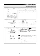
Calibration offset
Calibration Offset Function offset the difference between read temperature by this Controller and
actual measured temperature of Furnace. This Function enable parallel compensation in minus
or plus direction over the whole Controller Temperature Setting Range of this Equipment.
Example
When the measured Furnace temperature is lower than read temperature by 2
℃
:
The read temperature can be calibrated by inputting “Calibration Offset value -2.0” for 2
℃
compensation against actual Furnace temperature.
If read temperature is 200
℃
for example, its temperature will shift to 198
℃
after offset calibration.
※
This -2
℃
compensation is applied over the whole controller Temperature Setting Range
( FP
:
0
℃~
1200
℃
). Note that offset value might be changed depending on sample setting
arrangement and/or Target Temperature.
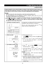
1 Turning the controller power off
Turn the ELB on the right side of the main unit [ON(
|
)].
The Bottom screen will show the current time.
While the unit is being operated, press the
key
longer to turn the controller power off.
2 Enter password.
↓
①
Press and hold
key.
Show [
UPASS
] on Bottom Screen and [
00
] flashing
on Top Screen.
②
Press
and
keys to enter password
“11” on Top Screen and press
key (The
password is fixed to “11”.).
3 Set Calibration Offset value.
↓
①
Press
key to display [
CAL
:
OS
] on Bottom
Screen then press
key.
②
Input offset value by
and
keys and
then press
key. You can enter an offset
amount up to ±15.0
℃
Example
Read temperature
:
200
℃
and actual measured
temperature
:
198
℃
⇒
Offset input value: -2.0
℃
※
Although you can input values up to the first decimal
place, the temperature indications and measured
temperatures will be rounded before indication.
③
Pressing the
key longer will return to the time
display screen.
Содержание FP102
Страница 67: ...64 12 Wiring diagram FP102 Wiring diagram Dotted line means optional parts ...
Страница 68: ...65 12 Wiring diagram FP302 Wiring diagram Dotted line means optional parts ...
Страница 69: ...66 12 Wiring diagram FP312 Wiring diagram Dotted line means optional parts ...
Страница 70: ...67 12 Wiring diagram FP412 Wiring diagram Dotted line means optional parts ...

