46
4. Operating procedure
Monitoring data
※
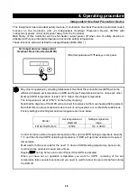
Check Integrated Power Consumption, integrated Operating hours and so forth by this
“Monitor
Item Display” function of this Equipment.
Can not modify any setting information shown on Top Screen.
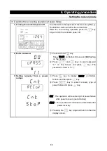
1 View integrated value on Top
Screen
※
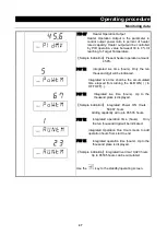
Monitor Items can be checked at Controller POWER
key ON or during operation state.
Press and Hold
key.
Monitor Items display screen activate and current Power
Consumption appear on Top Screen.
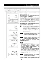
Use the
key shows the integrated power
consumption (MW) (kW), CO2 discharge amount (t) (kg)
heater operation amount (%), integrated live time (Unit:
10000 hours) (Unit: 1000 hours), integrated operation
time (Unit: 10000 hours) (Unit: 1000 hours).
Monitor Items display screen is ended, and Idle Screen
or Standby Screen is displayed finally.
KW
Current Power Consumption is calculated from
instantaneous power to power at one hour.
Power consumption may be indicated as [
0.0
]
and [
3.6
] alternately while temperature is
stable. Power consumption is indicated as
[
0.0
] during standby.
TOT
:
MW
Integrated power consumption (MWh). This is
indicated in a three-digit integer number.
TOT
:
KW
Integrated power consumption (kWh). This is
indicated in a three-digit integer number.
【
Sample
indication
】
Integrated
power
consumption:123,456kWh
CO2
:
_T
CO2 discharge amount (t). This is indicated in
a three-digit integer number.
CO2 discharge amount is calculated by multiplying
the power consumption by a discharge coefficient.
Confirm the discharge coefficient of different utility
companies with each company.
The initial value input is quoted from the substitutive
values, factory setting of 0.550(k-CO2/kWh), the
Environmental Ministry Press Release on 6
November 20013. For updates of the coefficients,
see the section, Setting and resetting the monitor
indication, item [3].
CO2
:
KG
CO2 discharge amount (kg). This is indicated
in a three-digit integer number.
【
Sample indication
】
CO2 discharge amount:456,789kg
Содержание FP102
Страница 67: ...64 12 Wiring diagram FP102 Wiring diagram Dotted line means optional parts ...
Страница 68: ...65 12 Wiring diagram FP302 Wiring diagram Dotted line means optional parts ...
Страница 69: ...66 12 Wiring diagram FP312 Wiring diagram Dotted line means optional parts ...
Страница 70: ...67 12 Wiring diagram FP412 Wiring diagram Dotted line means optional parts ...

