4-30
FRONT AND REAR BRAKES
CHAS
a
WARNING
NOTE:
30 Nm (3.0 m
S
kg, 22 ft
S
lb)
WARNING
CAUTION:
EAS00598
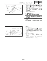
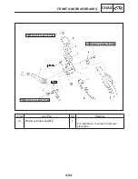
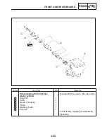
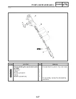
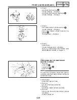
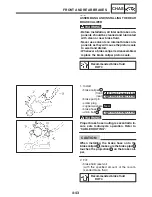
ASSEMBLING AND INSTALLING THE
FRONT BRAKE MASTER CYLINDER
S
Before installation, all internal brake com-
ponents should be cleaned and lubricated
with clean or new brake fluid.
S
Never use solvents on internal brake com-
ponents.
Recommended brake fluid
DOT 4
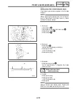
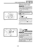
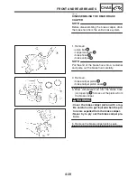
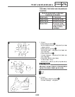
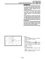
1. Install:
S
master cylinder kit
S
circlip
New
S
brake master cylinder
1
S
Install the brake master cylinder holder with
the “UP” mark facing up.
S
Align the end of the brake master cylinder
holder with the punch mark
a
on the handle-
bar.
S
First, tighten the upper bolt, then the lower bolt.
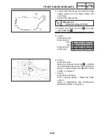
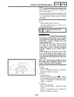
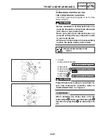
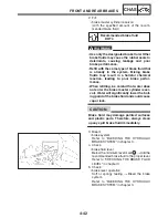
2. Install:
S
copper washers
1
New
S
brake hose
2
S
union bolt
3
Proper brake hose routing is essential to in-
sure safe motorcycle operation. Refer to
“CABLE ROUTING” in chapter 2.
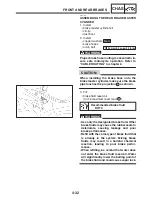
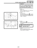
When installing the brake hose onto the
brake master cylinder, make sure that the
brake pipe touches the projection
a
on the
brake master cylinder.
Содержание FZ6-SS
Страница 1: ......
Страница 47: ...2 20 TIGHTENING TORQUES SPEC Cylinder head tightening sequence Crankcase tightening sequence...
Страница 52: ...2 25 COOLING SYSTEM DIAGRAMS SPEC 1 Radiator 2 Oil cooler COOLING SYSTEM DIAGRAMS...
Страница 53: ...2 26 COOLING SYSTEM DIAGRAMS SPEC 1 Water pump 2 Oil cooler 3 Radiator...
Страница 54: ...2 27 COOLING SYSTEM DIAGRAMS SPEC 1 Oil cooler 2 Water pump...
Страница 55: ...2 28 COOLING SYSTEM DIAGRAMS SPEC 1 Radiator 2 Thermostat...
Страница 56: ...2 29 ENGINE OIL LUBRICATION CHART SPEC ENGINE OIL LUBRICATION CHART...
Страница 57: ...2 30 LUBRICATION DIAGRAMS SPEC 1 Oil level switch 2 Oil cooler 3 Relief valve LUBRICATION DIAGRAMS...
Страница 58: ...2 31 LUBRICATION DIAGRAMS SPEC 1 Oil pump 2 Exhaust camshaft 3 Intake camshaft 4 Oil strainer...
Страница 59: ...2 32 LUBRICATION DIAGRAMS SPEC 1 Oil cooler 2 Oil strainer 3 Oil level switch 4 Oil pump...
Страница 60: ...2 33 LUBRICATION DIAGRAMS SPEC 1 Main axle 2 Oil pump 3 Relief valve...
Страница 61: ...2 34 LUBRICATION DIAGRAMS SPEC 1 Cylinder head 2 Intake camshaft 3 Exhaust camshaft 4 Crankshaft...
Страница 62: ...2 35 LUBRICATION DIAGRAMS SPEC 1 Main axle 2 Drive axle...
Страница 398: ...8 27 LIGHTING SYSTEM ELEC EAS00780 LIGHTING SYSTEM CIRCUIT DIAGRAM...
Страница 405: ...8 34 SIGNALING SYSTEM ELEC EAS00793 SIGNALING SYSTEM CIRCUIT DIAGRAM...
Страница 433: ...FZ6 SS FZ6 SSC WIRING DIAGRAM...
Страница 435: ......

