5-20
CYLINDER HEAD
ENG
NOTE:
NOTE:
NOTE:
EAS00222
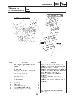
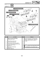
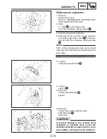
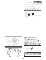
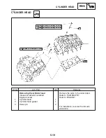
REMOVING THE CYLINDER HEAD
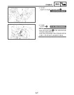
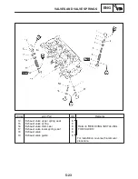
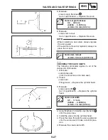
1. Remove:
S
cylinder head bolts
S
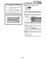
Loosen the bolts in the proper sequence as
shown.
S
Loosen each bolt 1 / 2 of a turn at a time. After
all of the bolts are fully loosened, remove
them.
EAS00229
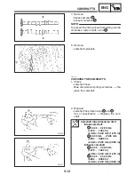
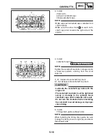
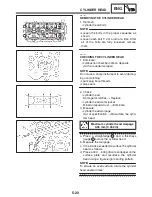
CHECKING THE CYLINDER HEAD
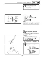
1. Eliminate:
S
combustion chamber carbon deposits
(with a rounded scraper)
Do not use a sharp instrument to avoid damag-
ing or scratching:
S
spark plug bore threads
S
valve seats
2. Check:
S
cylinder head
Damage / scratches
!
Replace.
S
cylinder head water jacket
Mineral deposits / rust
!
Eliminate.
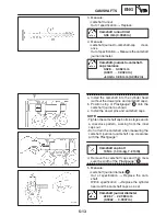
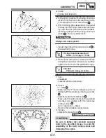
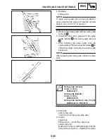
3. Measure:
S
cylinder head warpage
Out of specification
!
Resurface the cylin-
der head.
Maximum cylinder head warpage
0.05 mm (0.002 in)
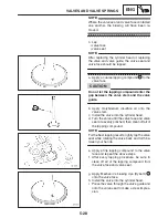
a. Place a straightedge
1
and a thickness
gauge
2
across the cylinder head.
b. Measure the warpage.
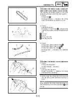
c. If the limit is exceeded, resurface the cylinder
head as follows.
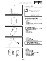
d. Place a 400
X
600 grit wet sandpaper on the
surface plate and resurface the cylinder
head using a figure-eight sanding pattern.
To ensure an even surface, rotate the cylinder
head several times.
Содержание FZ6-SS
Страница 1: ......
Страница 47: ...2 20 TIGHTENING TORQUES SPEC Cylinder head tightening sequence Crankcase tightening sequence...
Страница 52: ...2 25 COOLING SYSTEM DIAGRAMS SPEC 1 Radiator 2 Oil cooler COOLING SYSTEM DIAGRAMS...
Страница 53: ...2 26 COOLING SYSTEM DIAGRAMS SPEC 1 Water pump 2 Oil cooler 3 Radiator...
Страница 54: ...2 27 COOLING SYSTEM DIAGRAMS SPEC 1 Oil cooler 2 Water pump...
Страница 55: ...2 28 COOLING SYSTEM DIAGRAMS SPEC 1 Radiator 2 Thermostat...
Страница 56: ...2 29 ENGINE OIL LUBRICATION CHART SPEC ENGINE OIL LUBRICATION CHART...
Страница 57: ...2 30 LUBRICATION DIAGRAMS SPEC 1 Oil level switch 2 Oil cooler 3 Relief valve LUBRICATION DIAGRAMS...
Страница 58: ...2 31 LUBRICATION DIAGRAMS SPEC 1 Oil pump 2 Exhaust camshaft 3 Intake camshaft 4 Oil strainer...
Страница 59: ...2 32 LUBRICATION DIAGRAMS SPEC 1 Oil cooler 2 Oil strainer 3 Oil level switch 4 Oil pump...
Страница 60: ...2 33 LUBRICATION DIAGRAMS SPEC 1 Main axle 2 Oil pump 3 Relief valve...
Страница 61: ...2 34 LUBRICATION DIAGRAMS SPEC 1 Cylinder head 2 Intake camshaft 3 Exhaust camshaft 4 Crankshaft...
Страница 62: ...2 35 LUBRICATION DIAGRAMS SPEC 1 Main axle 2 Drive axle...
Страница 398: ...8 27 LIGHTING SYSTEM ELEC EAS00780 LIGHTING SYSTEM CIRCUIT DIAGRAM...
Страница 405: ...8 34 SIGNALING SYSTEM ELEC EAS00793 SIGNALING SYSTEM CIRCUIT DIAGRAM...
Страница 433: ...FZ6 SS FZ6 SSC WIRING DIAGRAM...
Страница 435: ......


