

7-21
FUEL INJECTION SYSTEM
FI
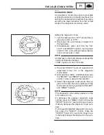
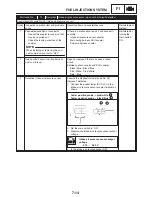
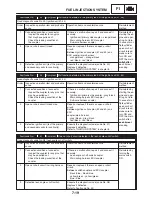
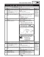
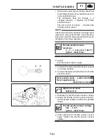
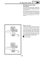
Battery positive terminal
!
red / black
Battery positive terminal
!
blue / yellow
1
2
Tester positive probe
!
red
Tester negative probe
!
red / blue
3
4
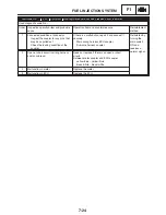
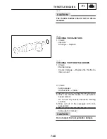
When the leads are disconnected, the voltage
check by the code No. 09 is impossible.
NOTE:
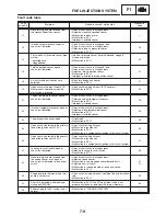
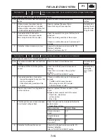
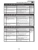
Fault code No.
43
Symptom
The ECU is unable to monitor the battery voltage.
Used diagnostic code No. 09 (fuel system voltage)
Order
Inspection operation item and probable
cause
Operation item and countermeasure
Reinstatement
method
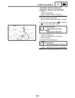
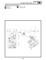
1
Connected condition of connector
Inspect the coupler for any pins that
may have pulled out.
Check the locking condition of the
coupler.
If there is a malfunction, repair it and connect it
securely.
Starting circuit cut-off relay coupler
(fuel injection system relay)
Fuel pump coupler
Injector coupler
ECU coupler
Reinstated by
starting the
engine and
operating it at
idle.
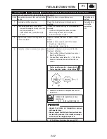
2
Malfunction in ECU
Fuel injection system relay is on.
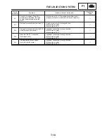
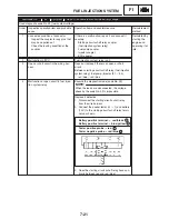
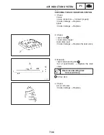
3
Open or short circuit in the wiring har-
ness.
Repair or replace if there is an open or short
circuit.
Between starting circuit cut-off relay (fuel injection
system relay), fuel pump, injector (#1
X
#4)
red / blue – red / blue
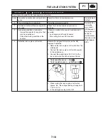
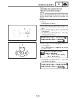
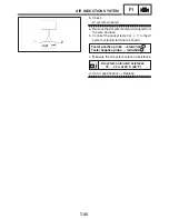
4
Malfunction or open circuit in fuel injec-
tion system relay
Execute the diagnostic mode (code No. 09)
Replace if defective.
1. Disconnect the starting circuit cut-off relay
from the wire harness.
2. Connect the pocket tester (
Ω
1) and battery
(12 V) to the starting circuit cut-off relay termi-
nals as shown.
3. Does the starting circuit cut-off relay have con-
tinuity between red and red / blue?
Содержание FZ6-SS
Страница 1: ......
Страница 47: ...2 20 TIGHTENING TORQUES SPEC Cylinder head tightening sequence Crankcase tightening sequence...
Страница 52: ...2 25 COOLING SYSTEM DIAGRAMS SPEC 1 Radiator 2 Oil cooler COOLING SYSTEM DIAGRAMS...
Страница 53: ...2 26 COOLING SYSTEM DIAGRAMS SPEC 1 Water pump 2 Oil cooler 3 Radiator...
Страница 54: ...2 27 COOLING SYSTEM DIAGRAMS SPEC 1 Oil cooler 2 Water pump...
Страница 55: ...2 28 COOLING SYSTEM DIAGRAMS SPEC 1 Radiator 2 Thermostat...
Страница 56: ...2 29 ENGINE OIL LUBRICATION CHART SPEC ENGINE OIL LUBRICATION CHART...
Страница 57: ...2 30 LUBRICATION DIAGRAMS SPEC 1 Oil level switch 2 Oil cooler 3 Relief valve LUBRICATION DIAGRAMS...
Страница 58: ...2 31 LUBRICATION DIAGRAMS SPEC 1 Oil pump 2 Exhaust camshaft 3 Intake camshaft 4 Oil strainer...
Страница 59: ...2 32 LUBRICATION DIAGRAMS SPEC 1 Oil cooler 2 Oil strainer 3 Oil level switch 4 Oil pump...
Страница 60: ...2 33 LUBRICATION DIAGRAMS SPEC 1 Main axle 2 Oil pump 3 Relief valve...
Страница 61: ...2 34 LUBRICATION DIAGRAMS SPEC 1 Cylinder head 2 Intake camshaft 3 Exhaust camshaft 4 Crankshaft...
Страница 62: ...2 35 LUBRICATION DIAGRAMS SPEC 1 Main axle 2 Drive axle...
Страница 398: ...8 27 LIGHTING SYSTEM ELEC EAS00780 LIGHTING SYSTEM CIRCUIT DIAGRAM...
Страница 405: ...8 34 SIGNALING SYSTEM ELEC EAS00793 SIGNALING SYSTEM CIRCUIT DIAGRAM...
Страница 433: ...FZ6 SS FZ6 SSC WIRING DIAGRAM...
Страница 435: ......


