


8-36
YES
NO
S
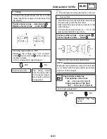
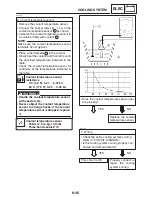
Clean the battery
terminals.
S
Recharge or re-
place the battery.
EAS00749
3. Main switch
S
Check the main switch for continuity.
Refer to “CHECKING THE SWITCHES”.
S
Is the main switch OK?
YES
NO
Replace the main
switch.
YES
NO
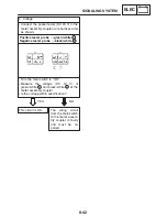
1. Horn switch
S
Check the horn switch for continuity.
Refer to “CHECKING THE SWITCHES”.
S
Is the horn switch OK?
Replace the left han-
dlebar switch.
EAS00796
CHECKING THE SIGNALING SYSTEM
1. The horn fails to sound.
EAS00795
4. Wiring
S
Check the entire signaling system’s wiring.
Refer to “CIRCUIT DIAGRAM”.
S
Is the signaling system’s wiring properly
connected and without defects?
YES
NO
Properly connect or
repair the signaling
system’s wiring.
Check the condition
of each of the signal-
ing system’s circuits.
Refer to “CHECK-
ING THE LIGHTING
SYSTEM”.
SIGNALING SYSTEM
ELEC
NOTE:
YES
NO
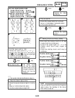
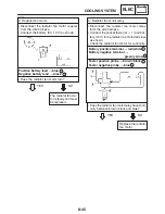
1. Backup, main, ignition, signal and tail fuses
S
Check the backup, main, ignition, signal and
tail fuses for continuity.
Refer to “CHECKING THE FUSES” in chap-
ter 3.
S
Are the backup, main, ignition, signal and tail
fuses OK?
Replace the fuse(s).
2. Battery
S
Check the condition of the battery.
Refer to “CHECKING AND CHARGING
THE BATTERY” in chapter 3.
Minimum open-circuit voltage
12.8 V or more at 20
_
C (68
_
F)
S
Is the battery OK?
EAS00739
EAS00794
TROUBLESHOOTING
S
Any of the following fail to light: turn sig-
nal light, brake light or an indicator light.
S
The horn fails to sound.
Check:
1. backup, main, ignition, signal, and tail fuses
2. battery
3. main switch
4. wiring connections
(of the entire signaling system)
S
Before troubleshooting, remove the following
part(s):
1. seat
2. front cowling inner panel (left and right)
3. fuel tank
4. side cover
S
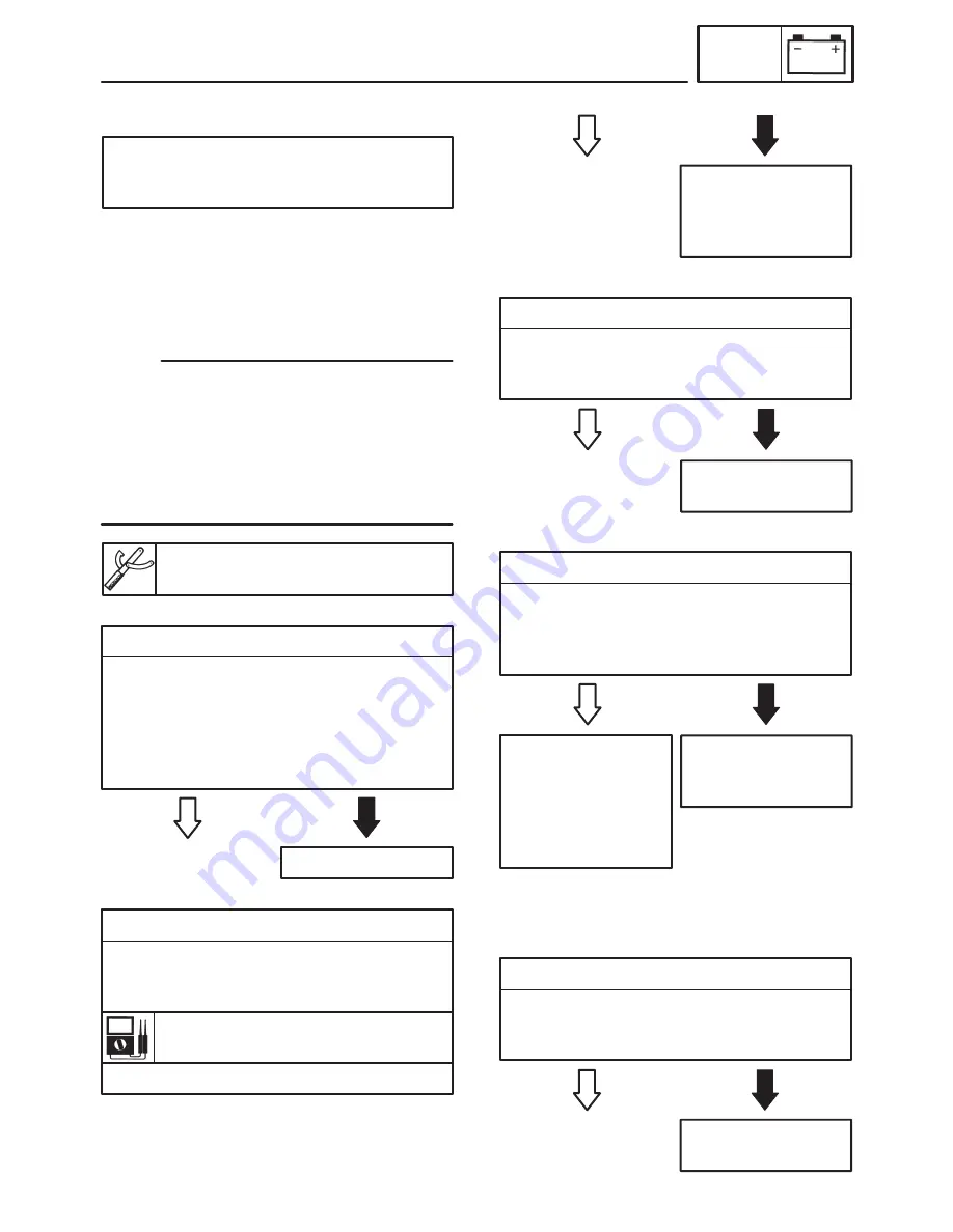
Troubleshoot with the following special tool(s).
Pocket tester
90890-03112, YU-3112
EAS00738
Содержание FZ6-SS
Страница 1: ......
Страница 47: ...2 20 TIGHTENING TORQUES SPEC Cylinder head tightening sequence Crankcase tightening sequence...
Страница 52: ...2 25 COOLING SYSTEM DIAGRAMS SPEC 1 Radiator 2 Oil cooler COOLING SYSTEM DIAGRAMS...
Страница 53: ...2 26 COOLING SYSTEM DIAGRAMS SPEC 1 Water pump 2 Oil cooler 3 Radiator...
Страница 54: ...2 27 COOLING SYSTEM DIAGRAMS SPEC 1 Oil cooler 2 Water pump...
Страница 55: ...2 28 COOLING SYSTEM DIAGRAMS SPEC 1 Radiator 2 Thermostat...
Страница 56: ...2 29 ENGINE OIL LUBRICATION CHART SPEC ENGINE OIL LUBRICATION CHART...
Страница 57: ...2 30 LUBRICATION DIAGRAMS SPEC 1 Oil level switch 2 Oil cooler 3 Relief valve LUBRICATION DIAGRAMS...
Страница 58: ...2 31 LUBRICATION DIAGRAMS SPEC 1 Oil pump 2 Exhaust camshaft 3 Intake camshaft 4 Oil strainer...
Страница 59: ...2 32 LUBRICATION DIAGRAMS SPEC 1 Oil cooler 2 Oil strainer 3 Oil level switch 4 Oil pump...
Страница 60: ...2 33 LUBRICATION DIAGRAMS SPEC 1 Main axle 2 Oil pump 3 Relief valve...
Страница 61: ...2 34 LUBRICATION DIAGRAMS SPEC 1 Cylinder head 2 Intake camshaft 3 Exhaust camshaft 4 Crankshaft...
Страница 62: ...2 35 LUBRICATION DIAGRAMS SPEC 1 Main axle 2 Drive axle...
Страница 398: ...8 27 LIGHTING SYSTEM ELEC EAS00780 LIGHTING SYSTEM CIRCUIT DIAGRAM...
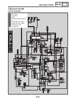
Страница 405: ...8 34 SIGNALING SYSTEM ELEC EAS00793 SIGNALING SYSTEM CIRCUIT DIAGRAM...
Страница 433: ...FZ6 SS FZ6 SSC WIRING DIAGRAM...
Страница 435: ......


