


3-24
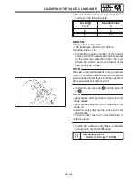
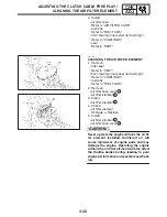
MEASURING THE COMPRESSION PRESSURE
CHK
ADJ
CAUTION:
WARNING
NOTE:
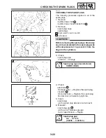
Before removing the spark plugs, use com-
pressed air to blow away any dirt accumu-
lated in the spark plug wells to prevent it
from falling into the cylinders.
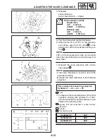
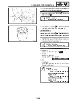
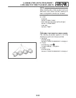
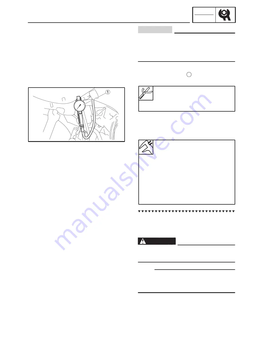
5. Install:
S
compression gauge
1
S
adapter
Compression gauge
90890-03081, YU-33223
Adapter
90890-04136
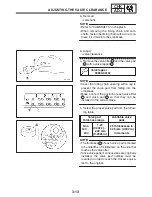
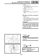
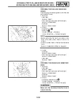
6. Measure:
S
compression pressure
Out of specification
!
Refer to steps (c) and
(d).
Compression pressure
(at sea level)
Minimum
1,350 kPa (13.50 kg / cm
2
,
13.50 bar, 191.87 psi)
Standard
1,550 kPa (15.50 kg / cm
2
,
15.50 bar, 220.46 psi)
Maximum
1,736 kPa (17.36 kg / cm
2
,
17.36 bar, 246.92 psi)
a. Turn the main switch to “ON”.
b. With the throttle wide open, crank the engine
until the reading on the compression gauge
stabilizes.
To prevent sparking, ground all spark plug
leads before cranking the engine.
The difference in compression pressure be-
tween cylinders should not exceed 100 kPa (1
kg / cm
2
, 1 bar, 14.22 psi).
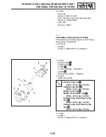
c. If the compression pressure is above the
maximum specification, check the cylinder
head, valve surfaces and piston crown for
carbon deposits.
Carbon deposits
!
Eliminate.
Содержание FZ6-SS
Страница 1: ......
Страница 47: ...2 20 TIGHTENING TORQUES SPEC Cylinder head tightening sequence Crankcase tightening sequence...
Страница 52: ...2 25 COOLING SYSTEM DIAGRAMS SPEC 1 Radiator 2 Oil cooler COOLING SYSTEM DIAGRAMS...
Страница 53: ...2 26 COOLING SYSTEM DIAGRAMS SPEC 1 Water pump 2 Oil cooler 3 Radiator...
Страница 54: ...2 27 COOLING SYSTEM DIAGRAMS SPEC 1 Oil cooler 2 Water pump...
Страница 55: ...2 28 COOLING SYSTEM DIAGRAMS SPEC 1 Radiator 2 Thermostat...
Страница 56: ...2 29 ENGINE OIL LUBRICATION CHART SPEC ENGINE OIL LUBRICATION CHART...
Страница 57: ...2 30 LUBRICATION DIAGRAMS SPEC 1 Oil level switch 2 Oil cooler 3 Relief valve LUBRICATION DIAGRAMS...
Страница 58: ...2 31 LUBRICATION DIAGRAMS SPEC 1 Oil pump 2 Exhaust camshaft 3 Intake camshaft 4 Oil strainer...
Страница 59: ...2 32 LUBRICATION DIAGRAMS SPEC 1 Oil cooler 2 Oil strainer 3 Oil level switch 4 Oil pump...
Страница 60: ...2 33 LUBRICATION DIAGRAMS SPEC 1 Main axle 2 Oil pump 3 Relief valve...
Страница 61: ...2 34 LUBRICATION DIAGRAMS SPEC 1 Cylinder head 2 Intake camshaft 3 Exhaust camshaft 4 Crankshaft...
Страница 62: ...2 35 LUBRICATION DIAGRAMS SPEC 1 Main axle 2 Drive axle...
Страница 398: ...8 27 LIGHTING SYSTEM ELEC EAS00780 LIGHTING SYSTEM CIRCUIT DIAGRAM...
Страница 405: ...8 34 SIGNALING SYSTEM ELEC EAS00793 SIGNALING SYSTEM CIRCUIT DIAGRAM...
Страница 433: ...FZ6 SS FZ6 SSC WIRING DIAGRAM...
Страница 435: ......


